Prepare the separation cable to IC-706
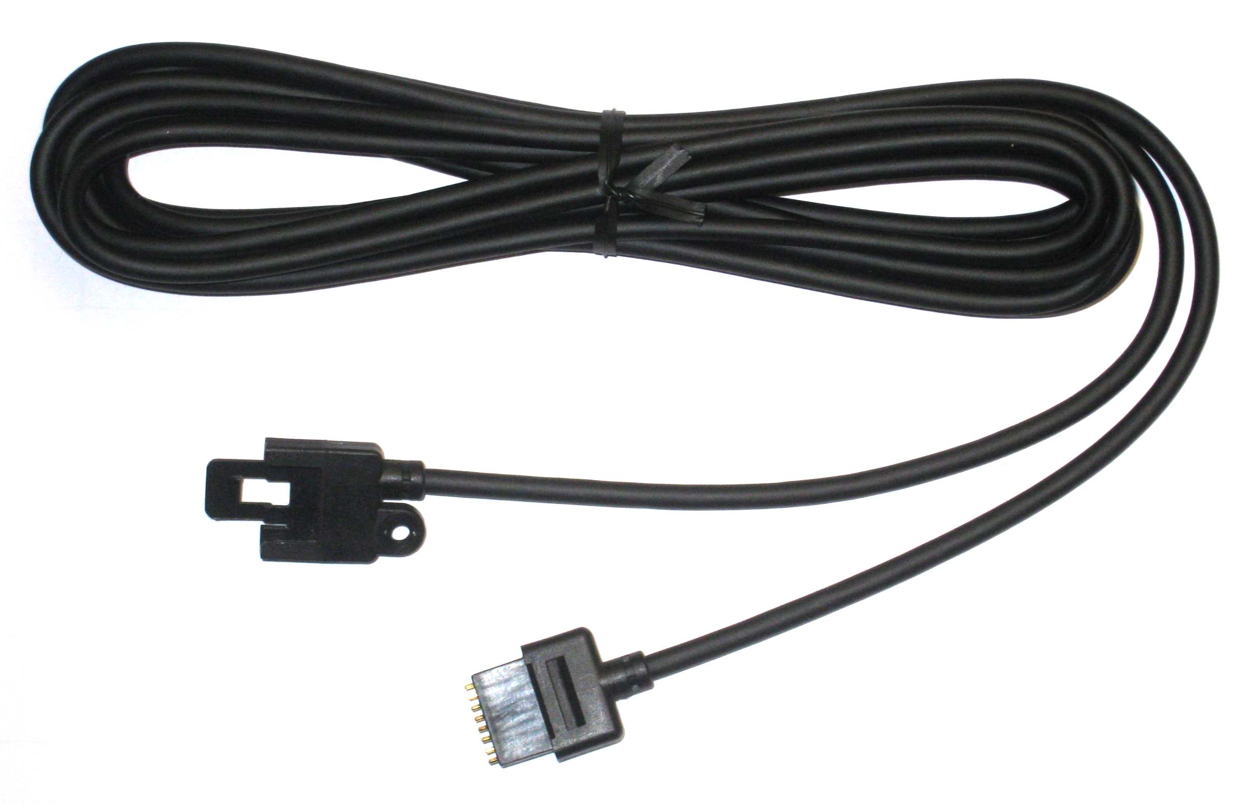
The cable between front and radio before it is cut apart. You have to buy this cable from your local ICOM-dealer (art no OPC-581 or OPC-587).
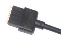
Connector at radio end.
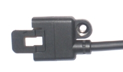
Connector at panel end.
- Cut the cable apart, don't make it longer then needed at radio end. The mic signal is sensitive of HF from antennas etc. as usually.
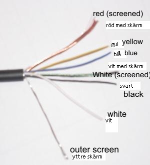
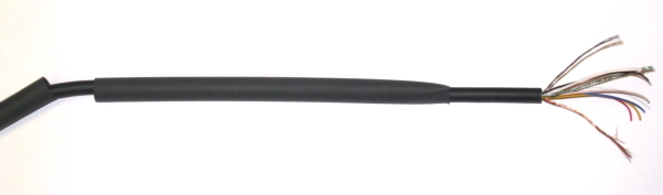
- Take away about 40 mm of the outer covering.
- Separate the shields from the inner wire, the red wire has a copper coloured shield and the white has a green shield. The shielded white wire is thinner than the white one without a shielding. That way you can identify them from each other. The outer shielding is not connected to the RRC.
- Cut all wire to about 20 mm. Take way about 3 mm of the cover from each wire and tin-plate them. It's not easy but it's possible.
- Also tin-plate the copper and green shielding.
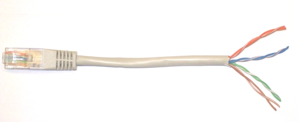
- Use the supplied CAT-5
cable cut of 10-15 cm from each connector and take away
40 mm of the outer cover.
- Separate the pairs.
- Take away 3 mm of the cover from each wire and tin-plate them.
- Identify the following colours:
2. Orange
3. Green/White
4. Blue
6. Green
7. Brown/White
8. Brown
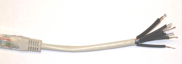
- Cut a piece of shrinking tube to each wire. Cut them short enough so they don't shrink from the heat of the solder iron.
- First tread a 100 mm long
6,4 mm shrinking tube on the separation cable.
- Then tread a 80 mm long 6,4 mm shrinking tube on the separation cable.
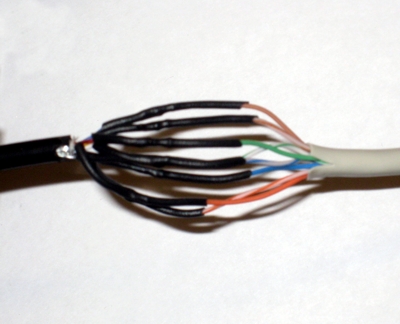
- Tread the shrinking tubes over the soldered joints and shrink them with hot air.
- Tread the 6.4 mm shrinking
tube over the joint and shrink it with hot air.
- Tread the second shrinking tube over the first and shrink them with hot air
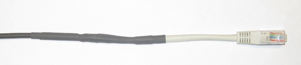
- The first cable is now
finished, Do the same with the other part. The one with the connector to the
panel.
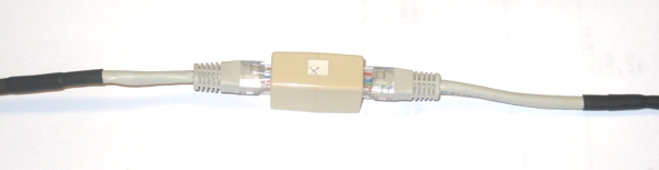
When you have finished both
cables , connect them together with the supplied RJ45 extender.
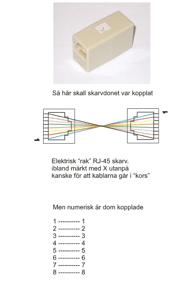
Extender wiring
- Check the cable with an ohm-meter. You should have connection from pin 1 at
radio end to pin 1 at radio end etc. Also check for short circuits between the
pins.
- Connect the cable between panel and radio and check the functionality. Don't forget the microphone. ( this should be done without involving the RRC.s at this moment.
When everything is OK you can connect the cables to the RRC:s
Remember that they are different.