Preparations of TS-2000
for remote control
(mode=8)
Please be aware of that the Kenwood numbering of the connectors are the opposite of what we use in the computer networks.
RJ12
RadioModular 4/4
Control
PanelDescription
1
2
1
TDO - serial
data 57600 bps from panel to radio
3
2
RDO - serial
data 57600 bps from radio to panel
4
3
GND
5
4
8V power to
control panel ( always present)
6
As you can see the Mic and speaker signal is not present in the cable above. Because of
that we have to make a splitted cable and connect the Mic and Speaker direct to the
RRC-1258. On the remote site you also have to make a splitted cable,
connected from the RRC to the Panel jack, Mic jack and to the Speaker jack.
Please be aware of that the Kenwood numbering of the connectors are the opposite of what we use in the computer networks.
8-pol Modular
3. MICE - Mic ground
4. MIC- Mic Signal
5. PTT
6. GND PTT
To make a more permanent installation it's possible to mount a 8 pin circular mic connector on the front of the RRC.
Attention! Always check for updated drawings before starting to make cables
Cables control panel RC-2000 to RRC-1258
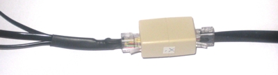
The Microphone is connected to the 2xRJ-45 extender.

Printer friendly drawing
=> Cables RRC-1258 to
Radio TS-2000
Printer friendly drawing =>
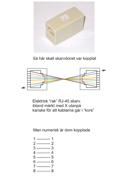
=> When you have finished
the cable production always test them with the 2xRJ-45 extender before
connecting them to the RRC:s.
Drawing 2xRJ-45 