WEB-Switch 1216E / Automatic antenna
switch
(updated 2010-08-12)
WEB-switch 1216 is also possible to use as a automatic antenna switch. When using the WEB-Switch as antenna switch it should be connected to the Transceivers CAT interface, today it's support Kenwoods CAT protocol an ICOM CI-V. Support for YAESU will be available later on. You program witch relay you want to be activated for resp. band via the internal WEB interface. You can also program the same relay to activated for more than one band, pracical if you use multiband antennas. On 80,40 and 10m it's possible to activade differnet relays for the different bandsegment witch means you can use have one antenna for the CW part and another for SSB. It's also possible combine the automatic function on some relays with the manual function others. The WEB-Switch asks the radio about witch frequency it's using, witch means that it works without HRD or other PC-software. Please be aware of that there is no HF-relays in the WEB-Switch, use external Koax-relays or control a existing antenna switch. Another example is control of 4-SQ COMTEK BOX to change beam headings etc. etc.
090625 - New firmware (v1.06) witch handles wildcard programming is available here=>
090519- New firmware (v1.04) where you can use manual control of the relays in combination with CAT control. Avalable here=>
From v1.05 is a wildcard functionality implemented witch makes it easier to combine different bands. Remember to use comma if you put more than one band/band segment on the same row.
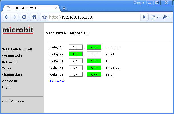
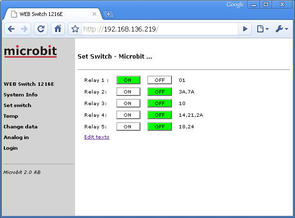
| 01 | 160m | The relay is activated for the entire 160m band |
| 35,36,37,38 | 80m | The relay can be activated at one or several bandsegment. |
| 3A | 80m | The relay is activated for the entire 80m band |
| 71,72,73 | 40m | The relay can be activated at one or several bandsegment. |
| 7A | 40m | The relay is activated for the entire 40m band |
| 10 | 30m | The relay is activated for the entire 30m band |
| 14 | 20m | The relay is activated for the entire 20m band |
| 18 | 17m | The relay is activated for the entire 17m band |
| 21 | 15m | The relay is activated for the entire 15m band |
| 24 | 12m | The relay is activated for the entire 12m band |
| 28,29 | 10m | The relay can be activated at one or several bandsegment. |
| 2A | 10m | The relay is activated for the entire 10m band |
| 50,51 | 6m | The relay can be activated at one or several bandsegment. |
Below follows an example where Wildcards is used.
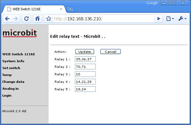
Relay 1 is activated on160m, Relay 2 on entire 80 and entire 40m, Relay 3 on 30m, Relay 4 on 20,15 and entire 10m, Relay 5 on 17 and 12m.
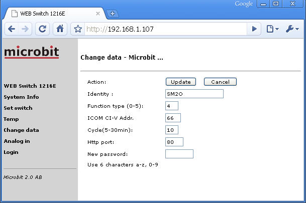
To activate the function for Kenwood and YAESU CAT protocol set "Function type" to 3 in the " Change data" menu. For ICOM CI-V set "Function Type" to 4 if you use the WEB-Switch standalone with the radio. If you use it together with a PC software (ex HamRadioDeLuxe) set "Function Type" to 5 then it will only listen to the serial data sent between the PC and the radio. The risk for unnessecary collisions on the serialbus eliminates this way. When used with ICOM a CI-V adress also must be set witch should match the one in the radio. The WEB-Switch serial port is always set to 9600 baud and is not changeable. Remember that you must be logged in to make changes.
To setup the realtionship between the relays and frequency band click on the link "edit texts" on the "Set switch" page. Put in the unique digits with needs to identify the frequency, see table above. If more than one frequency should activate a relay they should be separated with a comma. When the setup is finished click on the "Update" to save the changes, see below.
More information about the standard functions is available at WEB-Switch 1216E
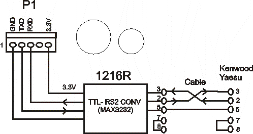
The schematic diagram below shows how the WEB-switch is connected to the ICOM CI-V interface.
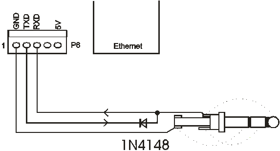
The schematic diagram below shows how to connect to Kenwood or Yaesu CAT interface with a RS-232 port.
You can use the RS232/TTL Adapter 1216R (available from the webshop) or make one
by your self.
If you use HamRadio Deluxe Pin 2 should not be connected in the D-sub, only pin 3 and 5 should be connected in parallel with the cable from the HRD PC. In this case the WEB-switch will only listen on the traffic between HRD and the Radio.
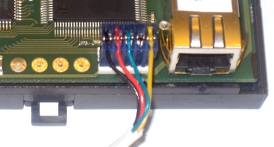
The picture below shows the connector where the CAT-cables should be connected. (The blue AMP-connector)