
This page is just for information for latest information check the pdf. manual
Front panel
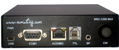
PWR LED
Green light is indicating normal status. When the green LED is flashing the unit is trying to connect to the Internet. Normally it only takes a few seconds. As long as the LED is flashing, connection can NOT be done. If the LED do not end flashing it’s probably something wrong with the network connection.USB
USB
The USB-interface is used to initially set up the IP-addresses. It can also be used for downloading new software ( can also be done via the WEB-interface).
COM 1
COM 1 can in special cases be used to set parameters and check statuses if USB or WEB can not be used. The COM 1 port can also be used for ex. rotator control as it can be configured as transparent serial port which is transfered between the boxes.
38400 Baud, 8 bits, No parity, 1 stop bit. ( to access config )
 |
No
1 |
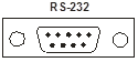
RS-232 Interface (9-pol D-sub female)
– |
AUX/MIC
The RJ-45 connector marked AUX/MIC is used for microphone connection or for connection of IC-703/706 control panel. In the box behind the connector is a set of straps with can be used to decide how the Connector should be configured, depending on radio or microphone. . The red and yellow LED:s are indicating SIP-status.
| Red | Yellowl | |
| Off | Incomming audio stream OK | SIP Disconnected |
| Flashing | – | SIP connection failed |
| Fixed light | Incomming audio stream is missing | SIP connection OK |
MIC/AUX-port configuration depends on the inside straps.
 |
No
1 |
AUX/MIC (RJ45)
Depending on inside straps |
TTL
TTL-port is used for connection of panel to Kenwood TS-480, RC-2000, IC-E2820 etc. (Control RRC)
The RJ-12 connector marked TTL is used primary for connection of TS-480, RC-2000, IC-E2820 control panels and in other cases where you need to connect via a TTL level (5V) port. The connector is configured so a straight cable can be used to a TS-480 control panel and to RC-2000.
 |
No
6 |
TTL (RJ12)
AF Output, Speaker 2W/8ohm |
TTL-port for connection of Kenwood TS-480, RC-2000, IC-2820, CI-V, FT-8×7 (Radio RRC)
RJ-12 connector marked TTL is used for connection of the cable which is normally connected between the control panel and the radio. It’s also used for CAT ´control of radios with 5V.s inputs eg. all ICOM with 3.5mm C-IV connector and FT-8×7 with the mini DIN-connector. The connector is configured so a straight cable can be used to a TS-480 control panel and to RC-2000.
|
No
6 |
TTL (RJ-12)
AF Input (TS-480) |
SP
SP- Speaker output (Control RRC).
At the control RRC:n the connector is used as a speaker output. It’s connected in parallel with the audio output pins in the MIC/AUX and TTL connectors. The connectors is a standard 3.5 mm for a mini stereo plug. There is no switch in the connector. The speaker output is 2W at 8 ohm.

SP- Speaker input (Radio RRC).
At the Radio RRC the speaker connector act as a input for the speaker signal from the radio. It is connected in parallel with the input pins in the MIC/AUX and TTL connector. The input has a resistive load of 50 ohms. The connectors is a standard 3.5 mm for a mini stereo plug. There is no switch in the connector.
CW
The CW knob is used for adjusting the CW-speed of the built in CW-keyer. There is no knob on the radio RRC.
Back side
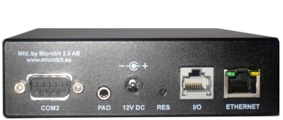
COM 2
COM 2 is used to connect a PC or Radio with RS-232 port. The communication parameters is set via the internal web. The control side RRC is equipped with a female connector which makes it possible to connect a straight RS-232 cable to the PC. The connector on the Radio RRC is a male.
COM2 – RS-232 Interface at Control RRC for PC connection
 |
No
1 |
RS-232 Interface (9-pol D-sub female)
– |
COM2 – RS-232 Interface at Radio RRC for connection to radios with RS-232 port.
|
No
1 |
RS-232 Interface (9-pol D-sub female)
– |
* Both Kenwood and Yaesu transceivers need the RTS-and CTS pins to be strapped together. JMP 3 inside the box can be used to strap them.
PAD – CW Paddle
PAD – Input. At the control RCC the input is used to connect a CW-paddle. The input is for a standard 3.5 mm stereo plug. Normally the left paddle is connected to the tip and the right paddle to the ring. Common is connected to the inner ring and house.
PAD – Output. At the Radio RCC the output is used to connect the output signal from the CW-keyer to the radio straight KEY input. The output is for a standard 3.5 mm stereo plug. A standard cable with 3.5 mm connector in both ends can often be used.
PWR
The unit is powered via the PWR connector with 10-18V DC.
Examples for power consumption at 12V D
| Local RRC (control) | Remote RRC (radio) | |
| IC-706 | up to 600mA depending on backlighter and audio volume | max 160 mA (110mA 10Mbit) |
| TS-480 | up to 500mA depending on audio volume | max 160 mA (110mA 10Mbit) |
| No control Panels |
up to 400mA depending on audio volume | max 160 mA (110mA 10Mbit) |
|
|
No
+ |
PWR
+10-15V (centre) GND |
RESET
A short press on the reset switch will reboot the unit. By pressing and keep the button pressed for 20 sec the unit reset to factory default settings (not all parameters).
Default IP-adress Control RRC: 192.168.0.227
Default IP-adress Radio RRC: 192.168.0.228
Default Netmask: 255.255.0.0
I/O
In the I/O connector is 3(2) inputs and 3 outputs, 8V and GND available ( see below). The connector is used for transferring signals from one box to the other. If the CW-keyer function is not used, the connector can be used for whatever controls needed in both directions. This I/O functions is configurabel under the I/O tab in the Web Interface.
The output transistor FDV301 can sink max 200mA, please install a external relay if it’s not strong enough.
 |
No
1 |
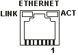
I/O (RJ-45)
IN 1 Active 0 (Dot vid CW*) |
* This are examples of usage, depending how the I/O settings are configured in the Web Interface
the inputs and outputs can have different functions
** Only available at Control RRC.
ETHERNET
The unit can be connected to both 10 and 100 Mbit/s Ethernet based TCP/IP network.
 |
No
1 |
Ethernet (RJ45)
Out [+] |