
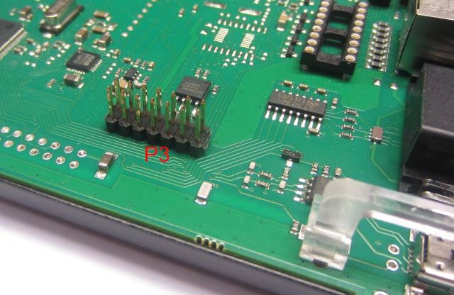
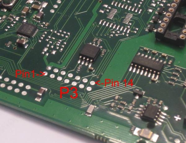
The Wifi Interface can be installed in all versions of the RRC-1258 and RRC-1258MkII and in both the Control-RRC and the Radio-RRC. The WiFi Interface is connected to P3.
Installation in RRC units produced after summer 2012 it very easy, no soldering or modifcation are needed only a plastic plug has to be removed from the housing.
PCB:s produced before summer 2012 do not have the pin header mounted, so you have to mount the pinheader before you can attach the WiFi PCB. The pin header has to be soldered to the PCB. If you need a pinheader it can be order via the webshop =>here.
Note! If you have a brand new system, set it up with cabled network connections before you install the WiFi Interface to keep it as simple as possible to start with.
Instructions
1 – Install the latest firmware in the RRC ( v.2.65 or later). Check the installation with your browser.
2 – Disconnect all cables from the RRC, disassemble the RRC.
If the pinheader P3 is already in place you can go direct to step 10 below.
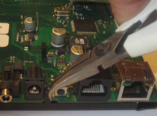
3- After removing the top, remove the CW-speed knob and remove the screws besides Com1. You also have to bend up the metal piece in the back of the box besides the reset button, witch holds the pcb in place. After that you can lift out the pcb.
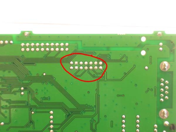
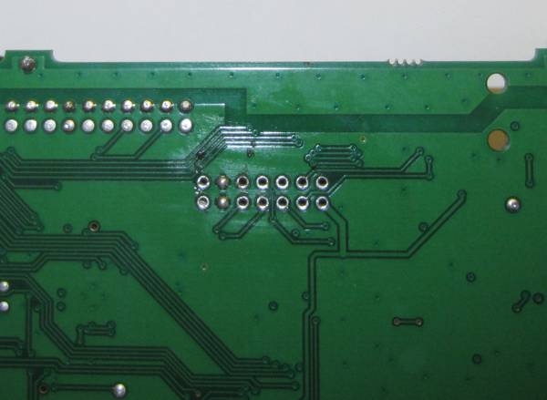
4 – Locate P3 in your RRC. Depending on the generation of the PCB, P3 has either 10 or 14 pins. New pcb:s have 14 pins older 10. The Pinheader delivered together with the WiFi Interface has 14 pins. If P3 on your PCB has only 10 pins carefully cut of 4 pins (2×2) from the Pinheader.
5 – Turn the pcb so you have the components down, apply more Tin to all 10/14 pads.
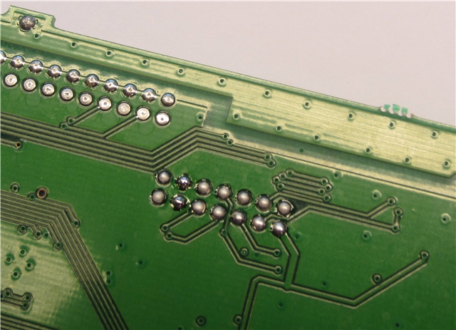
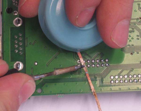
6 – Use soldering braid to remove Tin from all holes exept Pin3 and 4, Pin 3 and 4 are connected to the ground plane and is almost impossible to clear out so if your not an expert with an fully equiped workshop just leave it there, don’t even try to remove the Tin from them.
7 – Put the pin header in place , put a piece of cardboard between your fingers and the pinheader (so you do not burn your fingers) and apply much heat to pin 3 and 4 until the pinheader comes in position. When the pinheadeer is in position solder the rest of the pins to the pcb.

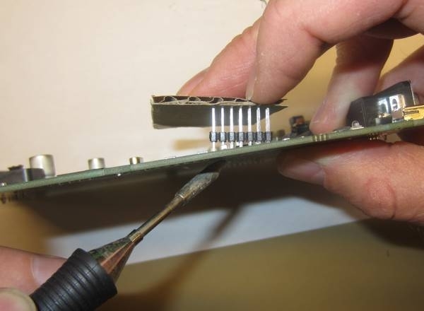
8- Inspect your soldering so there is no short circuits between the pins.
9- When modifying PCB where P3 has a 10 pol pin header, you need to add a wire for the reset signal to pin 8 also.
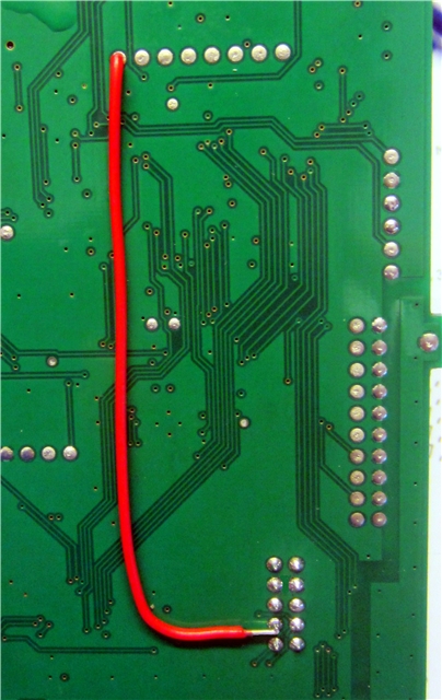 |
Note! This wire should only be applied on PCB where P3 has a 10 pol pin header
|
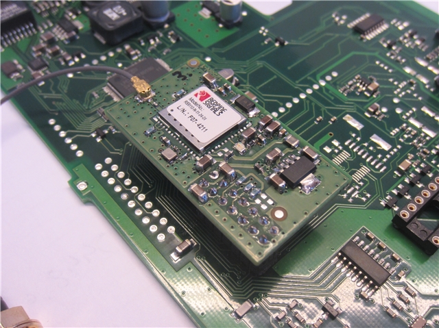
10 – Put the WiFi Interface in place as shown on the pictures. Be careful and If your pcb has a 10 pin header be extra careful when you put the WiFi Interface in place so Pin 1 is connected pin 1 etc. If you put it wrong the Wifi module and or the main PCB may be damaged, and warranty does not cover damages caused by incorrect assembly.
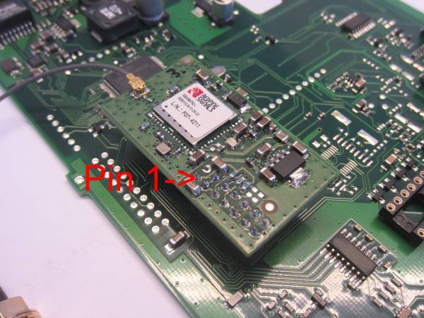
11 – Attach the antenna to the SMA conector.
12 – Apply power and Ethernet to the RRC, the LED on the Wifi interface should be red.
13 – Browse your RRC and check the Info page. The “Wifi network” status line should show “Not connected”. (before Wifi was installed it showed Not installed)
14 – How to set up the WiFi connection is showed in the users manaual.
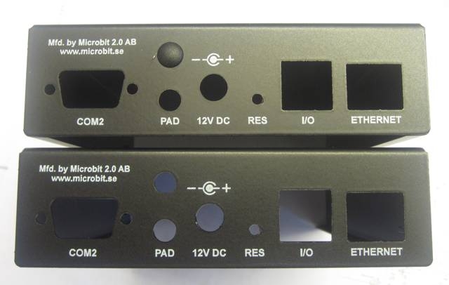
15 – When it works you can drill a hole ( 6.5 mm) in the back of the top part of the housing for the SMA antenna connector. Note that the SMA connector is not totally circular, it has a flat side to prevent unwanted rotation. If you have time you can drill a slightly smaller hole ( 6.0 mm) and use an small file to enlarge the hole so it fits exactly to the SMA connector.
Later production lots have the hole for the SMA connector already drilled, some versions has it covered by a plastic cover, then you only need to remove the cover.