If you have a RRC:s with hardware v7 or later you do NOT need to read this, check the users manual for setup
Hardware configuration
The hardware prepararions is a little bit more complicated for the IC-E880 with hardware version before v7 eg v5 and v6, as some modifications must be done at the Remoterig circuit boards. The HM-133 adapters must be mounted and a wire must be connected, more info below.
Connections
The cabling is quite simple and can be done with simple RJ connectors. Be aware of that the HM-133/880 adapter boards must be used
Drawings of the connection cables can be found below.
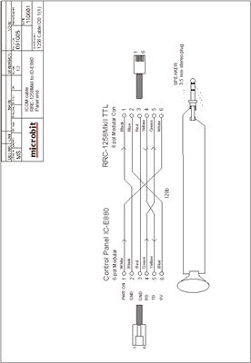
Control-RRC:
You have to make the control cable I20a to connect between the Control panel and the RRC TTL connector. Mark up the cable so you connect the connectors to the right unit, it will not work if you try to use it connected backwards.
- The microphone can be connected direct to the RRC AUX/MIC connector if you have a microphone with RJ-45 connector.
- The speaker is connected direct to the RRC SP-jack with a 3.5 mm stereo plug.
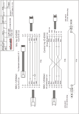
Radio-RRC:
You have to make the control cable I19a to connect between the Radio-RRC and the Radio. Mark up the cable so you connect the connectors to the right unit, it will not work if you try to use it connected backwards.
- Between the RRC AUX/MIC connector and the radios microphone jack you can connect a standard patch cable (CAT5 or CAT6).
- The speaker signal from the radios external speaker jack to the RRC SP jack is connected via a standard “off- the-shelf” cable with 3.5 mm stereo plugs in both ends.
HM-133/880 Microphone adapter pcb
If you have a RRC-1258MkIIs you can buy the HM-133/880 adapter pcbs which are needed for the function together with the IC-E880.
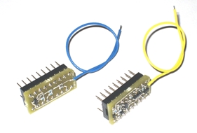
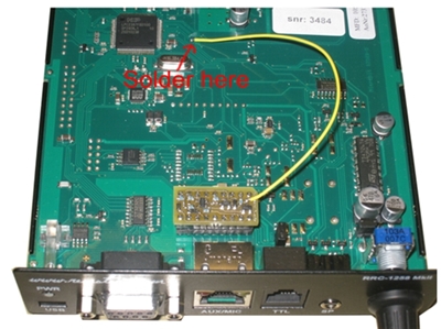
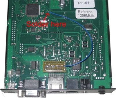
The small pcbs are mounted in the strapping sockets which means that no red straps are needed. The pcb with the yellow cable are mounted in the Control-RRC and the pcb with the blue cable are mounted in the Radio-RRC. The yellow and blue cables need to be solder to one point on the RRC pcb. See pictures below. Be sure to remove power when solder. There is no settings that need to be changed after mounting the pcbs.
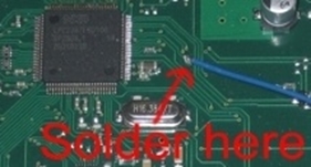 |
There is one solder pad which is significantly bigger than the other via holes to the right of the CPU over the Crystal. That’s the one which the cables should be soldered to. |
Control-RRC
Radio-RRC
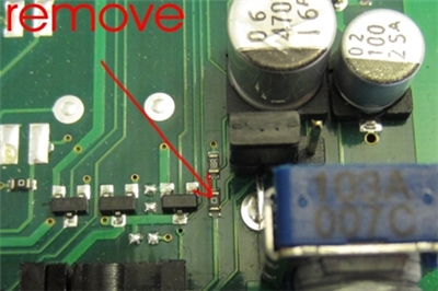
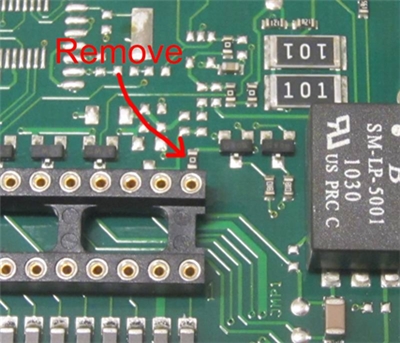
Modifications of the Control-RRC circuit board
One resistor must be removed and a wire must be solder between two pads. You need a fine solder iron and a short piece of insulated thin wire and maybe a little piece of tin. Don’t use any soldering braid or pumps they may damage the pcb.
– Remove the resistor by heating the ends of the resistor, alternate from left to right end staying a few seconds at each end until the component come loose.
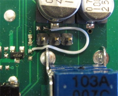
– Solder the thin insulated wire between the solder pads as shown on the picture below.
Modifications of the Radio-RRC circuit board
One resistor must be removed and a wire must be solder between two pads. You need a fine solder iron and a short piece of insulated thin wire and maybe a little piece of tin. Don’t use any soldering braid or pumps they may damage the pcb.
– Remove the two 0 ohms “resistors” by heating the ends of the resistor, alternate from left to right end staying a few seconds at each end until the component come loose.
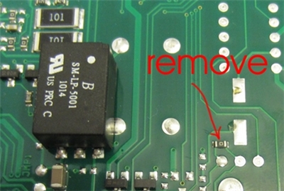
– Solder the thin insulated wire between the solder pads as shown on the picture below.
Cables
Use the link below to download schematics in pdf format.
Schematics