
Note! If you have RRC:s of version V7 or later no mods are needed and you do not need to look at this page.
If you have a RRC:s of hardware version of V6 or earlier, there is two ways of adapting the RRC-1258MkII(s) to work togheter with FT-857 if you want to remote control it from the control panel, when it’s separated from the Radio. One way is to make a few small modifications to the pcb. The other is to make splitted cables. If you modify the pcb:s the cables are more straight forward and you can connect microphone direct to the RRC for example. The solution with splitted cables is not so good looking but it works also.
Use the Tabs above to choose the info you need.

Modification of the PCB:s
The hardware prepararions are a little bit more complicated for the FT-857 as some modifications must be done at the Remoterig circuit boards. See instruction below. If you later want to use IC-706 or TS-480 and want to connect the speaker audio via the the control cable you need to reverse the hardware modifications, for other setups the modifications do not have any impact.
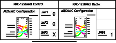
If you do not want to modify the pcb you can make some splitted Y-cables. Not so nice looking but a working solution. Schematics for the cables (Y10a,Y10b) can be found under the “Splitted cable” Tab above. Note that the straps should be set different when using the Y-cables.
Connections
The cabling is quite simple and can be done with simple RJ and modular connectors. The 5 wire control cables are the same on control and radio end, but be aware of that the cables must be connected as shown in the schematics.
Drawings of the connection cables can be found here.
Drawings for the cables Y8a,Y8b
Control-RRC:
– You have to make the control cable Y8a to connect between the Control panel and the RRC TTL connector. Mark up the cable so you connect the connectors to the right unit, it will not work if you try to use it connected backwards.
– The original microphone can be connected direct to the RRC AUX/MIC connector.
– The speaker is connected direct to the RRC SP-jack with a 3.5 mm stereo plug.
Radio-RRC:
– You have to make the control cable Y8a to connect between the Radio-RRC and the Radio. Mark up the cable so you connect the connectors to the right unit, it will not work if you try to use it connected backwards.
– Between the RRC AUX/MIC connector and the radios microphone jack you can connect a standard screened patch cable (CAT5 or CAT6).
– The speaker signal from the radios external speaker jack to the RRC SP jack is connected via a standard “off- the-shelf” cable with 3.5 mm stereo plugs in both ends.
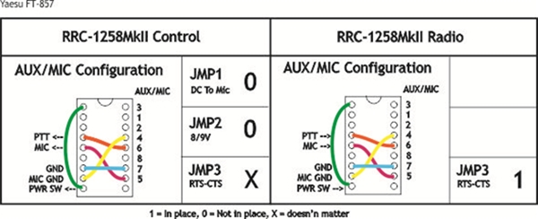
Modifications of the Control-RRC circuit board
One trace on the pcb need to be cut to make it work. Locate the trace between the TTL connector and the Speaker connector ( see picture below). Use a sharp screew driver or the tip of a knife to carefully cut the trace.
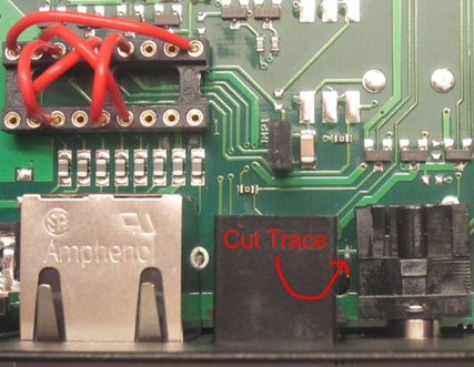
Modifications of the Radio-RRC circuit board
One 0 ohm resistor (jumper) must be removed and a wire must be solder between two pads. You need a fine solder iron and a short piece of insulated thin wire and maybe a little piece of tin. Don’t use any soldering braid or pumps they may damage the pcb.
– Remove the 0 ohm “resistor” by heating the ends of the resistor, alternate from left to right end staying a few seconds at each end until the component come loose.

If you later want to reverse the modification, you can just solder a small copper wire between the pads instead of the 0R resistor.
– Solder the thin insulated wire between the solder pads as shown on the picture below.
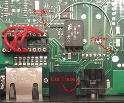
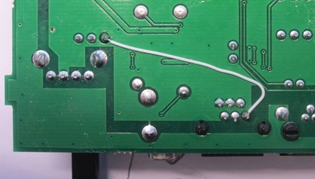
If you later want to reverse the modification (the cut trace) it’s easiest to remove the PCB from the box and solder a wire between the two points showed in the picture below.
Splitted cables.
If you do not want to modify the pcb as described under the “Mod PCB:s” Tab above you can make some splitted Y-cables. Not so nice looking but a working solution. Schematics for the cables (Y10a,Y10b) can be found below. Note that the straps should be set different when using the Y-cables.
