
Down below follows more info about the WEB-Switch.
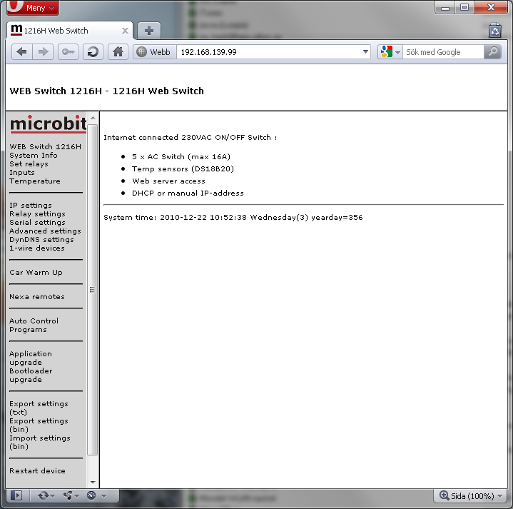
Above: First page of the WEB Switch internal web server. In the example it has the IP address 192.168.139.9. To the left there is hyper links to other internal information pages.The picture shows a web switch equipped with the additional modules, “Car Warm Up”, “Nexa remotes” and “Auto Control Programs”(aka ACP).
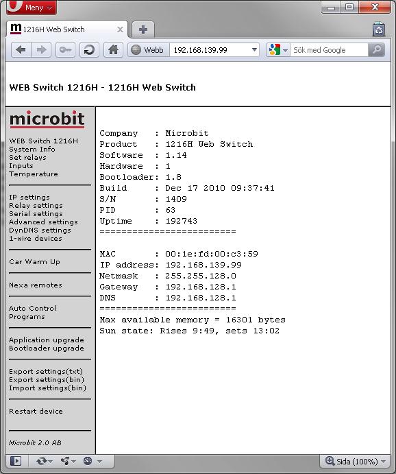
Above: Behind the Link “System Info” you will find information about the unit. Firmware versions, IP-addresses etc. There is also info about sun rise and set(requires correct date/time, longitude and latitude)
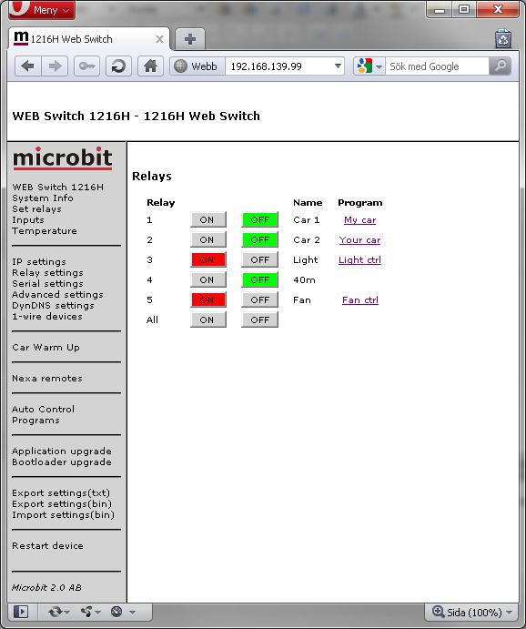
Above: On the web page behind the link “Set relays” you can control the relays, a activated relay’s button is red, a inactivated is green. A short describing text can be set to each relay. If a relay is controlled by a module like Car Warm Up then its name is shown under “Program”. In this case relay 1 and 2 are controlled by the Car Warm Up module, relay 3 and 5 are controlled by two separate Auto Control Programs. There is also buttons for turning on or off all relays simultaneously(unless “Only one relay ON simultaneously” on “Relay settings” is set to “Yes”) Be aware of that you need to be logged in to control the relays.
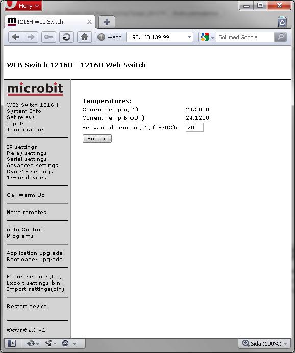
Above: Behind the link “Temperature” you will find readings from connected 1-wire temperature sensors, or “N/A” if no reading is available. You can also set the wanted temperature if you use the WEB-switch for temperature control.(“Function type” on page “Advanced settings” set to “Heating control, cycle” or “Fan control”.) More info can be found here.
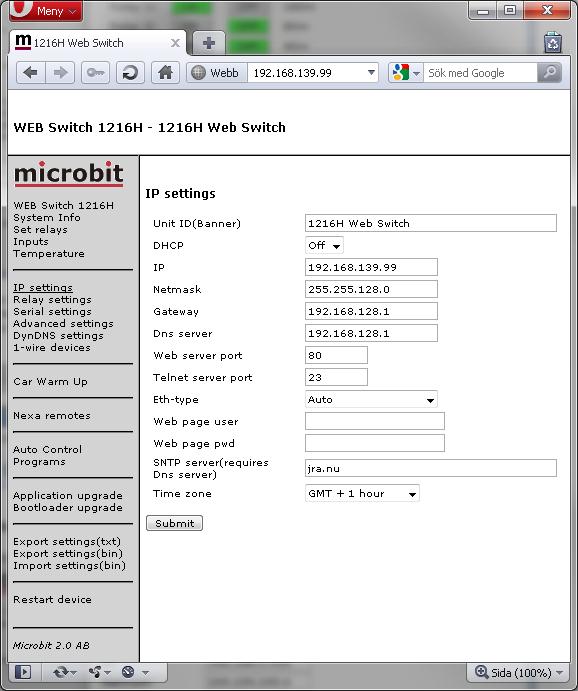
Above: Behind the IP Settings link a “Unit ID” can be set, all normal IP settings, WEB server port, Ethernet type and login information for the web pages. Changing the “Web server port” for the internal web server from default port 80 to something else can be convenient in combination with routers and port forwarding where port 80 already is in use. For the web switch to have correct date/time you need to set up a SNTP server as well as Time zone.
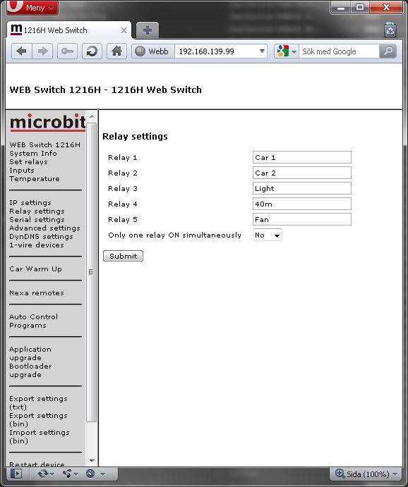
Above: The menu “Relay settings” is for editing the describing texts of the relays, and for selecting if only one relay may be activated at a time. Be aware of that you need to be logged in to editing the texts.
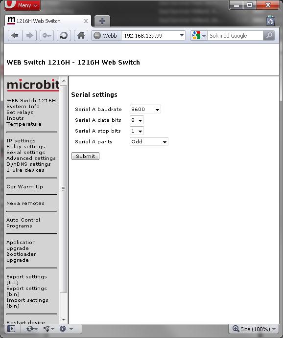
Above: The Uart settings page is used to set parameters for the serial port (mainly used for CAT controlled antenna switching).
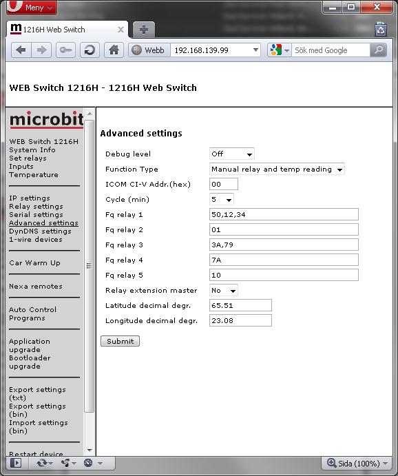
Above: Behind the link “Advanced settings” you can make some initial settings.
Function type select how you want to use the WEB-Switch. The switch above is set to be used with manual relay control with the possibility to read the temperature sensors. There are also modes for Heating control, Fan control, Antenna Switching. Cycle set is for “Heating control” how long the total control cycle is, in slow systems like a house you may use 15-20 min, in a small cupboard shorter may times fits better. If cycle time is set to 0 the cycle time is set to 20 s. If you just use the WEB-Switch just for reading temperatures set cycle time to 0 to get shortest possible update time.
The “Fq” settings are for controlling antenna switches based on frequency bands. More info about that can be found here.
Enabling “Relay extension master” makes it possible to connect two web switches via the 1-wire interface and control up to 10 relays based on frequency bands.
Latitude and longitude are needed for the ACP sun up/down based controls of the relays.
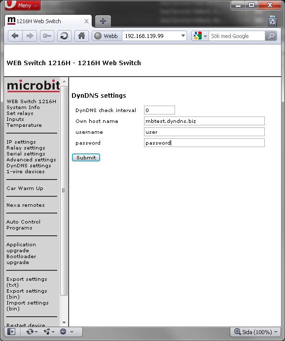
Above is shown the DynDNS settings needed if the switch is to be accessed from the public Internet while being on a dynamic IP address.
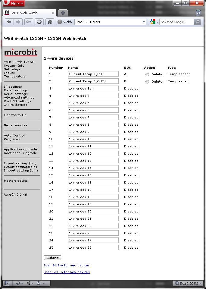
Above is the 1-wire devices’ settings. It is possible to name the devices, delete devices, as well as scanning the buses(A/B) for new devices. As default number 1 and 2 are scanned for temperature sensors and named like seen above for compability reasons.
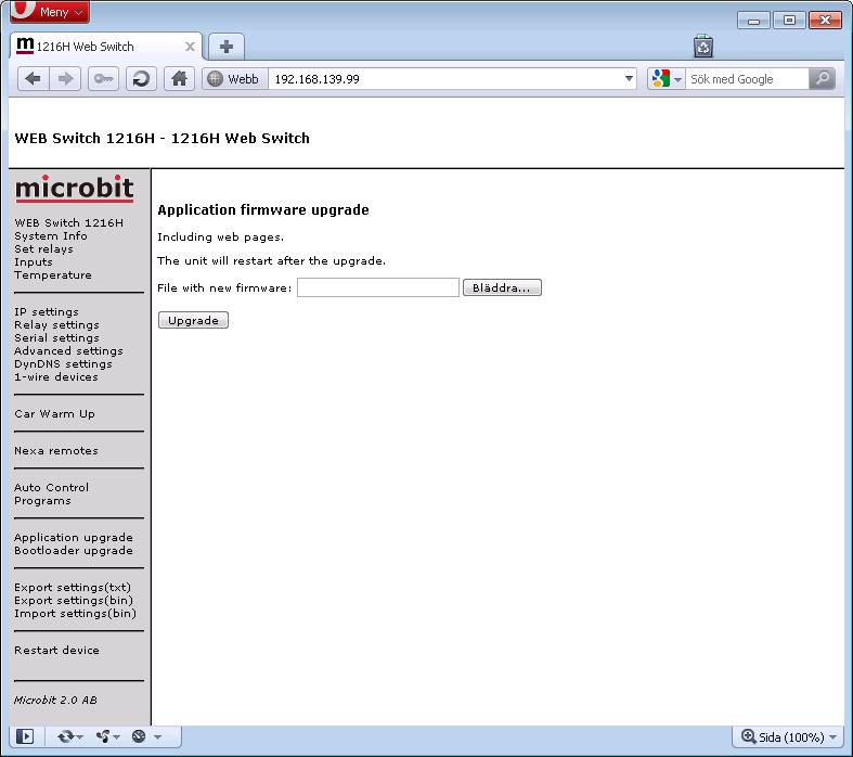
Above is the page allowing for firmware upgrade of the Web switch.The firmware is the Web switch’s main program.

Above is the page which allows upgrading of the Web switch’s bootloader. The bootloader is responsible for booting up the Web switch as well as doing the actual upgrade of the Web switch’s firmware.
“Export settings(txt)” exports the basic edition’s settings to a file in text format.
“Export settings(bin)” exports all settings(all modules) to a file in a binary format. It can be used for backing up a web switch’s settings, or for transferring settings from one unit to another.
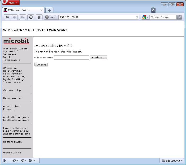
“Import settings(bin)” imports all settings(all modules) from a binary file. Note that all existing settings are overwritten!
“Restart device” is used to restart the device 😉


