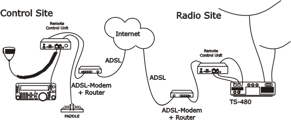
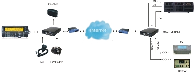
The technical solution for TS-480 is the same as for IC-703/706 and TS-2000. All those transceivers is built in the way that that the control panel is working separated from the radio unit it self. We replace the cable between panel and radio with two RRC-1258MkII, one connected to the control panel and one connected to the radio. No PC is needed at all. When you press the Power button on the panel, the radio comes to life at the remote side and sound and panel info flows across the internet between the pair of RRC-1258MkII:s. The technical solution is the same as modern SIP-based IP telephones + a little extra. The look and feel of the panel is the same as if the panel was directly connected to the radio. The TS-480 is even more simple to adapt than IC-703/706 because you do not need any special cable. You can make the cables by your self using simple and cheap RJ-45 and RJ-12 cables.
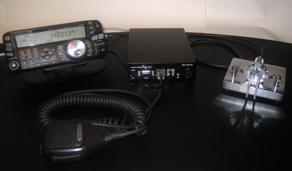
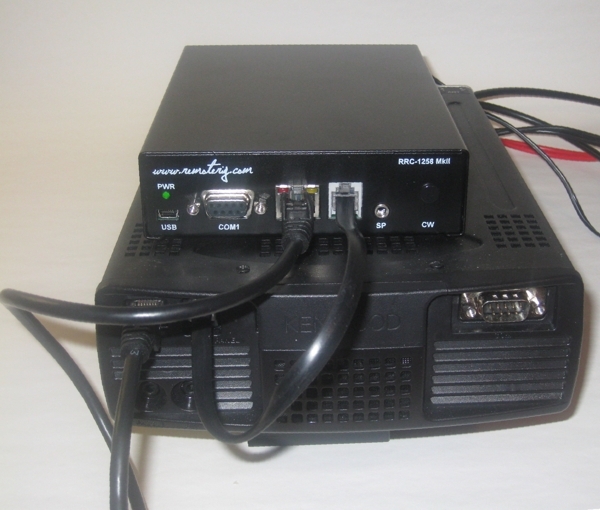
TS-480 control panel and RRC-1258MkII
TS-480 Radio unit and RRC-1258MkII
Preparations of TS-480 for remote control (mode=5)
(updated 10-09-15)
All necessary signals between the panel and the radio is connected thru the 6 wire cable between the control panel and the radio. We just need to cut it apart and connect a RRC-1258MkII in each end. The following signals is represented in the cable. Convenient for travelling is that the speaker is already present on the back of the control panel so there is no need for a extra speaker even if a separate speaker gives a much better audio (recommended for fixed use).
6-pol Modular
1. SPK GND- Speaker ground
2. 8V power to control panel ( always present)
3. GND
4. RDO – serial data 57600 bps from radio to panel
5. TDO – serial data 57600 bps from panel to radio
6. AF – Audio to speaker.
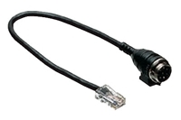
The easiest way to make these two cables from Control panel to Control RRC TTL-jack and from Radio-RRC TTL-jack to radio is to cut the cable supplied by Kenwood into two pieces. You only have to crimp two new 6/6 modular connectors on the cables. Don’t make the one between Radio-RRC and radio to long.
The long Microphone extension cable supplied by Kenwood can also be used between Radio-RRC AUX/MIC jack to the radio Mic jack. Probably you need to cut in later to prevent it from picking up HF from your antennas.
If your TS-480 is provided with a microphone with RJ-45 connector you can connect it directly to the AUX/MIC jack on the Control RRC. If it’s provided with a circular 8 pin connector you can used the adapter cable MJ-88 supplied by Kenwood with your TS-480 as a adapter between the Mic and the AUX/MIC jack.
One problem is that Kenwood have changed the layout of the Mic input during production and there are two different connections.
| Connection type 1 | Connection type 2 |
|
8-pol Modular
|
8-pol Modular
|
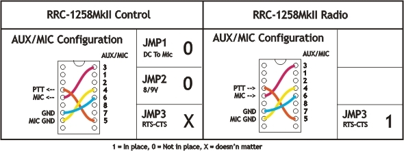
| 3. MIC- Mic Signal 4. MICE – Mic ground 5. PTT 6. GND PTT |
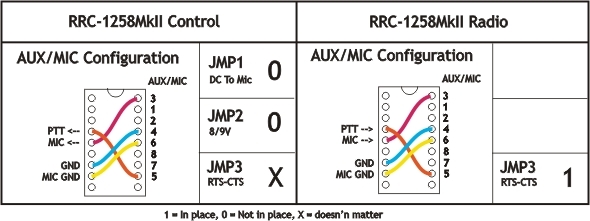
3. MIC- Mic Signal 4. GND PTT 5. PTT 6. MICE – Mic ground |
We have got it confirmed by Kenwood that from serial number 70600056 an onwards it’s Connection type 1 which is produced. If you want to confirm it the simplest way is to measure with and ohm meter before doing the strapping. Do not connect anything to power. Open the Radio-RRC, connect the supplied patch cable between the Radio-RRC and the Mic-Input of the radio. Measure with and good ohm meter between the point marked 6 (see below) and the chassi of the TS-480. If you get less than 1 ohm you have connection type 1. From the pin marked 4 you should have about 3 ohm to chassi. If you get the opposit values you have connection type 2.
After you have decide which connection type you have you can do the strapping according to the pictures below. There is no catastrophe if you use the wrong one, you will recognize it later when going into air. If you have used the wrong one you the radio will be sensitive for RF from the antenna and your voice will be distorted
Before connecting the cables to radio and control panel you need to do some strappings inside the RRC:s. For instructions of how to open the RRC:s see “Open the box / straps” page. Down below is the strappings that need to be done described.
Connection type 1
Connection type 2

Attention! Always check the users manualfor updated drawings before starting to make cables
The Control-RRC are powered with a simple 13.8V (10-18V) power supply. The display (backlighter) and speaker amplifier needs lot power so use min 1A.
The Radio-RRC could be powered with a separate Power supply or the same as the radio. If you use the Radio PS make sure you have a 1A fuse on the output to the RRC. Do not connect it direct to a 20-40A PS the cable will melt if something happens.