
Configuring the RRC-1258MkII and RRC-1258
The purpose of this page is to give a overview of the functions in the RRC-1258 system.
For setup of your unit you should use the information in the Users manual which always have the latest information.
This page will only be updated if major changes are done.
The “Submit” and “Apply changes” buttons
After each setup pages is done press “submit” to temporary store the new settings. When you do that a new red “Apply changes” button appears on the pages. You can now change other parameters on other pages but the new settings will not take effect until you press “Apply changes”. When you do that the unit will reboot and start up with the new settings. If you change your mind after clicking on submit you can click on “Restart device” on the left, then the RRC will restart without changing any settings.
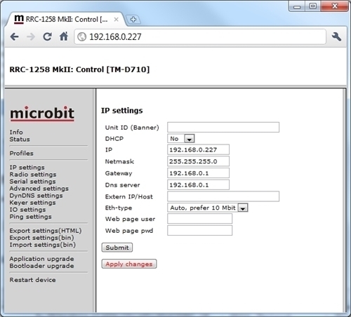
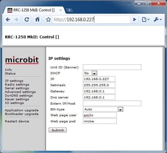
IP Settings
The IP Settings menu is used to setup the initial IP parameters needed for the unit to connect to the TCP/IP networks. Connect to the RRC internal web server and click on the “IP Settings” link to the left. Down below the settings are described more in details. Save the new settings by pressing ‘Submit’

| Unit ID (Banner) | Unit ID (Banner) Here you can put whatever text you want. Used to identify different units |
| DHCP | Select No for fixed IP or Yes for DHCP. DHCP can be practical in Control end but Fixed IP is preferred in Radio end. |
| IP | IP-address (only when fixed IP-addr is used) |
| Netmask | Net mask (only when fixed IP-addr is used) |
| Gateway | Gateway (only when fixed IP-addr is used) |
| Dns server | DNS-address (only when fixed IP-addr is used) |
| Extern IP/Host | Not used in normal installations |
| Eth Type | Type of ethernet connection. Auto = The RRC select automatically highest possible speed Auto prefer 10FDX = Same as Auto but selects 10 Mbit if it’s possible(1) 10HDX = 10 MBit/s half duplex (2) 10FDX = 10 MBit/s full duplex (2) 100HDX = 100 MBit/s half duplex (2) 100FDX = 100 MBit/s full duplex (2) (1) 10 Mbit network is not sending out as much noise as 100 Mbit networks so it is preferable. It’s also default. (2) The switch you connect to must also be set manually to the same value otherwise it will not work properly, avoid this settings. |
| Web page user | If you want to password protect your units you can put the username here. If you leave this field empty the RRC will not ask for password. The status pages will always be possible to see even when the unit is password protected. |
| Web page pwd | In this field you put the password. |
Radio Settings
The Radio settings menu is used to setup the RRC to act together with different radios. The settings must be done in both Control an Radio end. Down below the settings are described more in details. Save the new settings by pressing ‘Submit’.
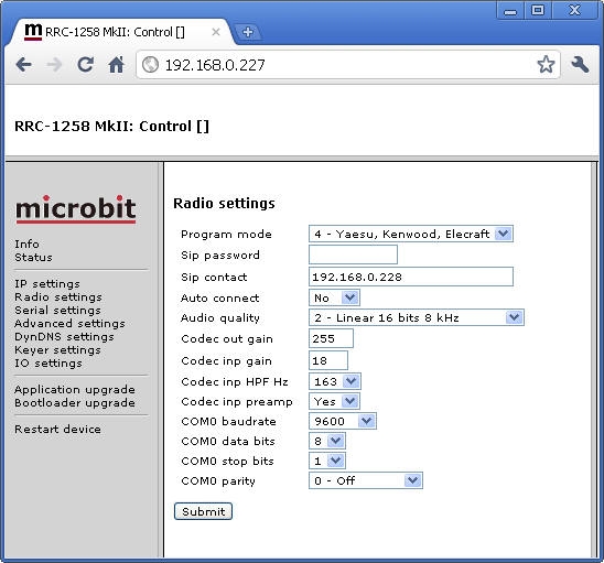
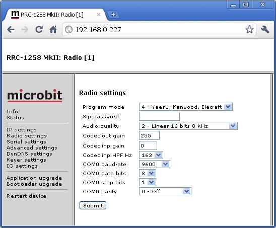
| Program mode | Sets the program mode depending on connected radio 0 – Transparent (for repeater links etc.) 1 – ICOM CI-V for ICOM, when CI-V protocol is used. 2 – IC-706 for IC-706 with detached control panel 3 – FT-8×7,FT-1000x for FT-817, FT-857, FT-897, FT-1000 etc. 4 = Yaesu, Kenwood, Elecraft for Kenwood CAT, Yaesu FT-2000, Elecraft etc. 5 = TS480 for Kenwood TS-480 with detached control panel 6 = Not in use 7 = ICOM IC-R2500 for IC-R2500, IC-2725 with detached control panel. 8 = TS2000 for TS-2000 with RC-2000 control panel. 9 = IC-E2820 for IC-E2820 |
| Control panel | Yes at control end No at radio end. ( not available in the RRC-1258MkII ) |
| Sip password | Protect your rig. Should be same in both ends. ( default is no password set) |
| Sip contact | Sets the IP or DynDNS name to the radio QTH. ( only shown in control RRC ) |
| Auto connect | When ON the Control RRC will connect to Radio-RRC immediately after power up in mode 0,1,3,4. ( only shown in control RRC ) |
| Audio Quality | Sets the audio quality depending on available bandwidth ( default = 2 Linear 16 bits 8 kHz) see detaild info on the codecs page. |
| Codec inp HPF Hz | Sets the High pass filter frequency of the codec input. Lower values get better audio response at low frequencys which can be useful when listen to FM/BC-stations. ( default is 163 Hz) |
| Codec Out gain | Always 255 255 is no attenuation 254 = 0,5 dB attenuation eg 0,5 dB/step |
| Codec Inp gain | Should be 18 at control end for high level electret microphones. Should always be 0 at Radio RRC. 0 = 0 db gain increasing 0,75 dB/step (See more info at the radio tabs) |
| Codec inp preamp | Switch the 20 dB Codec Preamp ON/OFF, only available at Control RRC (See more info at the radio tabs) |
| COM 0 baudrate | Sets the baudrate for the radio communication ( max 57600) IC-703/706 =19200 IC-E2820 = 38400 DX-SR8 = 38400 TS-480 = 57600 TS-2000 = 57600 For other radios = depending on Radio settings, HamradioDeLuxe settings etc. |
| COM 0 data bits | Sets the data bits ( 7 or 8 default = 8 ) |
| COM 0 stop bits | Sets the stop bits (1 or 2 default = 1) |
| COM 0 parity | Sets if parity bits should be used. ( default = 0 Off ) 0 = Off (Not used) 1 = Odd 2 = Even 3 = Forced “1” 4 = Forced “0” |
Serial Settings
The serial settings dialog is used to control the behaviour of the extra serial ports which can be use for CAT control, rotator control etc. The RRC_1258MkII has two (COM1 and COM2) extra serial channels, RRC-1258 has one (COM1). COM 1 can always be used as a extra transparent serial channel. connection is done to the front D-sub marked COM 1. Be aware of if you use COM 1 as a transparent serial channel you can not use it for configuration. COM 2 which is available only on MkII can be used as an extra serial channel if the RRC:s are set to program mode 2,5,7,or 8 in other modes it’s already in use for the radio control. COM 1 can be used for optional purposes. COM 1 and COM 2 can be configured to have a little bit different behaviour depending on what they will be used to see below. The settings must be done in both Control an Radio RRC:s. Down below the settings are described more in details. Save the new settings by pressing ‘Submit’.
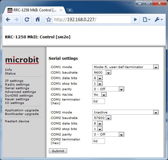
| COM 1 mode | Sets if the back serial port should be transferred transparent between the two RRC:s. and the behaviour of the transfer. Inactive (Not activated default) Mode-1 = COM1 activated. Data is sent char by char, needs lot of bandwidth if lot of data is sent) Mode-2 = COM1 activated. Mode 2 is used if CI-V control will be used for IC-703/706 at the same time as you use Control panel. Mode-3 = COM1 activated. Data is sent when there is a pause between messages. Mode-4 = COM1 activated. Used if you want to use CAT control of the TS-480 or TS-2000 at the same time as you use the control panel. Mode-5 = COM1 activated. Mode 5 is used if you want to decide the terminator character by your self. The terminator character is the one which initiate the data packet to be sent to the opposite box. Mode-6 = CAT to COM2 activated ( only avalable in Radio-RRC) makes it possible to connect other hardware which needs to speak to the radio via COM1 at the Radio-RRC. The IP-data from control side COM2 and local COM1 will be intelligent mixed (in sequence) before sent to local COM2. Data from local COM2 goes to both local COM1 and to the controlside COM2 via IP. Can be used for MicroHam, the WebSwitch, Power Amplifier etc. This function is for Yaesu, Kenwood and Elecraft only. |
| COM 1 baudrate | Sets the baudrate ( max 57600) |
| COM 1 databits | Sets the data bits ( 7 or 8 ) |
| COM 1 stop bits | Sets the stop bits (1 or 2) |
| COM 1 parity | Sets if parity bits should be used. 0 = Off (Not used) 1 = Odd 2 = Even 3 = Forced “1” 4 = Forced “0” |
| COM1 cts/rts | Set = Yes if you want the CTS input to be transferred to RTS output in the Opposite RRC. (default = No) |
| COM1 terminator mode 5 | Sets the terminator character used in Mode-5 to initiate the packet to be sent. It’s should be entered HEX-format. |
| COM 2 mode
Attention ! COM 2 is only available as an extra serial port in RRC-1258MkII. In RRC-1258 it’s always in parallel with COM 0. |
Sets if the back serial port should be transferred transparent between the two RRC:s. and the behaviour of the transfer. Inactive (Not activated default) Mode-1 = COM1 activated. Data is sent char by char, needs lot of bandwidth if lot of data is sent) Mode-2 = COM1 activated. Mode 2 is used if CI-V control will be used for IC-703/706 at the same time as you use Control panel. Mode-3 = COM1 activated. Data is sent when there is a pause between messages. Mode-4 = COM1 activated. Used if you want to use CAT control of the TS-480 or TS-2000 at the same time as you use the control panel. Mode-5 = COM1 activated. Mode 5 is used if you want to decide the terminator character by your self. The terminator character is the one which initiate the data packet to be sent to the opposite box. |
| COM 2 baudrate | Sets the baudrate ( max 57600) |
| COM 2 databits | Sets the data bits ( 7 or 8) |
| OM 2stop bits | Sets the stop bits (1 or 2) |
| COM 2 parity | Sets if parity bits should be used. 0 = Off (Not used) 1 = Odd 2 = Even 3 = Forced “1” 4 = Forced “0” |
| COM2 terminator mode 5 | Sets the terminator character used in mode 5 to initiate the packet to be sent. It’s should be in HEX-format. |
Advanced Settings
The latest software releases has user configurable port settings to make it possible to use several RRC:s on a LAN and also use the RRC if you have SIP based IP telephony using port 5060 in place.
You need to know what you are doing when you change ports especially on the remote end so that you don’t disconnect yourself. If you do a factory reset from the menu, all settings go back to default.
To change the advanced settings, click on the link ‘Advanced settings‘ to the left in the web browser when you have made the connection to the RRC. Here you can change the settings, and save them by pressing ‘Submit’.
Change web and telnet ports ONLY if you have to due to other services / RRC:s on your LAN. If you lose the connection a car ride might be the next thing you do 😉
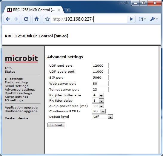
| UDP Cmd port | Port used for the Command channel (default = 12000) |
| UDP Audio port | Port used for the audio channel (default= 11000) |
| SIP Port | Port used for the SIP sessions ( default= 5060) |
| Web server port | Port for the internal http web server (default = 80) |
| Telnet server port | Port for the internal telnet server ( default = 23) |
| Rx Jitter buffer size | Is used to control the handling of the incoming audio stream small values = short delays , higher values means better tolerance against bad Internet connections but the delay will increase. “Rx Jitter buffer size” must be larger then “Rx Jitter delay”. The figures indicate RTP packages. (default = 4 packets x 10 ms when Audio Quality = 2 ) |
| Rx Jitter delay | Is used to control the handling of the incoming audio stream small values = short delays , higher values means better tolerance against bad Internet connections but the delay will increase. “Rx Jitter delay” must be smaller then “Rx Jitter buffer size”. The figures indicate RTP packages. (default = 3 packets x 10 ms when Audio Quality = 2 ) |
| Audio packet size (ms) | Sets the size of the audio packets in ms. If you have a good Internet connection ( > bandwidth) i both ends or using your own LAN or WLAN for both units it’s possible to reduce the packet size down to 1 ms. Smaller packets means decreased delay but increased bandwidth. Short delays is important specially for CW operation. ( default = 20 ms) |
| Continous RTP Tx | Needs to be switch on ( =Yes ) if VOX will be used. It means that the audio stream is sent continuously from the Control RRC to the Radio RRC. This can be a security problem for some user because un audio is sent from the mic to the Internet continuously. ( default = 0 )
In the Radio RRC it can also be activated. Some mobile (3G) networks take some time before they open up for a continues audio stream which end up in problems when releasing the PTT. Continues RTP stream often solves this problem. |
| Debug level | Not used , should be = 0ff. |
Detailed information about the relationships between the parameters is available in this document =>
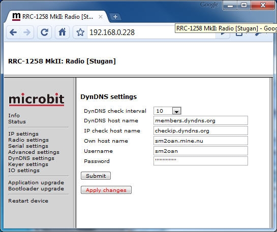
Dynamic DNS (Dyn DNS)
A built in DynDNS Client is implemented in the RRC-1258MkII. Dynamic DNS is only interesting in the radio end if you have a Internet Service Provider which use Dynamic IP. The DynDns client checks what IP address the router has got from the ISP and sends the updated information to DynDNS:s DNS server. When using DynDNS you can use your own “Host name” instead of a IP address in the SIP contact field and you don’t need to bother if the IP at the radio site changes. You need to register a account (free) at www.dyndns.com to start with. After that you enter the same information at the Internal DynDNS web page in the RRC. Remember that host names starting with a digit is not allowed. “DynDNS check time” sets how often the IP-check should be done. DynDNS says it should be 10 minutes or longer. If you select “0ff” the DynDNS client is not activated. There are other providers of the same service but RRC-1258 only supports DynDNS today.
Keyer Settings
A very powerful function for remote CW operation is implemented in the RRC-1258MkII. The system is now able to handle delays and jitter caused by Internet in a unique way. The Keyer settings link will only appear in control RRC.
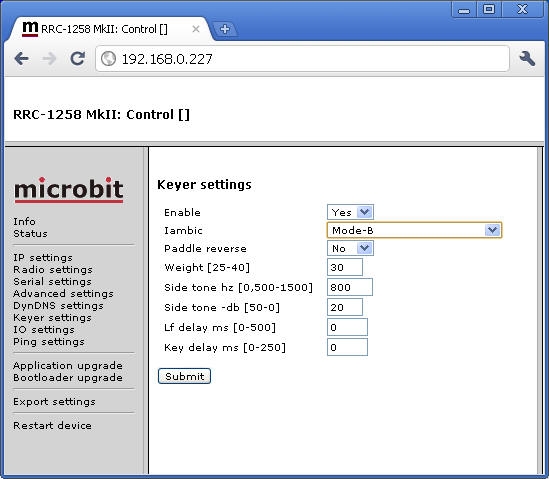
| enable | No = keyer disabled / Yes = keyer enabled |
| speed wpm | sets the speed in wpm ( Not shown in RRC-1258MkII ) |
| iambic | sets different keyer mode. old type (like squeece keyer) iambic A iambic B (most common, default) iambic B with automatic character spacing |
| paddle | No = normal (default) Yes = reversed |
| weight | sets the ratio between dot and dash 30 = 3.0/1 (default) |
| sidetone hz | sets the sidetone frequency (default = 800 Hz) If you set 0 Hz No local side tone is generated, can be used to test how the CW sounds if you enable side tone in the radio and send with memory keyer or PC. |
| sidetone dB | sets the level of the sidetone (default = 20) |
| lf delay ms | sets the mute delay time for the audio from the RX. Start with same as the ping time (default = 0) |
| key delay ms | sets the delay before the start of the keying at radio end (default = 0) |
I/O Settings
The Inputs and outputs in both the Control and Radio RRC is configurable to meet different needs.
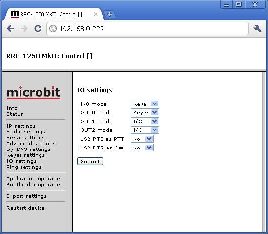
At the Control RRC the following configurations can be done
| IN0 mode | Input 0 in the I/O connector can be configured to a few different functions I/O = The input is transferred from Control to Radio RRC. Keyer = The input is used for Straight key or external keyer PTT = The input is used as ext. PTT ( foot switch etc.) |
| OUT0 mode | Output 0 can be configured for one of two functions. I/O = Indicatind that SIP connection is up. Keyer = The output act as a local output to for the keyer to key an local radio. ( default is I/O) |
| OUT1 mode | Output 1 can be configured for one of two functions. I/O = The output follows Input 1 from the Radio-RRC. Keyer = The output act as a local output to for the keyer to key an local radio. ( default is I/O) |
| OUT2 mode | Output 2 can be configured for one of two functions. I/O = The output follows Input 2 from the Radio-RRC. Keyer = The output act as a local output to for the keyer to key an local radio. ( default is I/O) |
| USB RTS as PTT | ON/OFF The USB virtual comports RTS signal is used as ext PTT (from logging software etc.) |
| USB DTR as CW | ON/OFF The USB virtual comport DTR signal is used as ext keyer input. (from logging software etc.) |
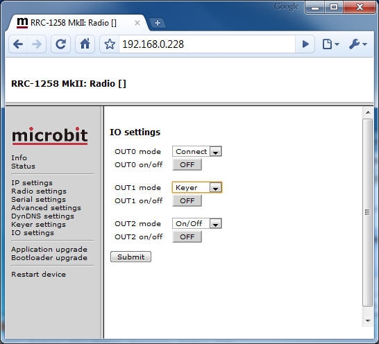
At the Radio RRC the following configurations can be done
| Out 0 mode | The output 0 in the I/O connector can be configured to one of five different functions
I/O = The input from the control RRC is transferred to the output of the Radio RRC. |
| Out 1 mode | The output 1 in the I/O connector (or tip on the PAD con) can be configured to one of five different functions
I/O = The input from the control RRC is transferred to the output of the Radio RRC. |
| Out 2 mode | The output 2 in the I/O connector (or ring on the PAD con) can be configured to one of five different functions
I/O = The input from the control RRC is transferred to the output of the Radio RRC. |
* If the ON/OFF buttons are pushed the output change will be immediate. But will resume to last saved position after power on. If you want the changes to be permanent use the “apply changes” button.
Ping Settings
As an extra security function there is an ping watchdog function implemented which is quite common in network equipments. It can be set to ping a IP address and when it does not get any answer, it will make a hard reboot of the RRC. The status off the ping watchdog can be checked at the status page. This function is only available on the Radio-RRC.
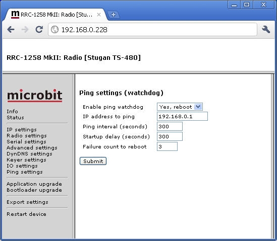
| Enable ping watchdog | Enables the function. No = Function is disabled Yes, test = Function enabled but it will not actually reboot, can be used for test Yes, reboot = Function is enabled. |
| IP address to ping | IP address to ping is entered here, In normal cases use the Gateway IP |
| Ping Interval (seconds) | Interval between the ping is sent. (1-65535, default 300 s) |
| Startup delay | Delay before the first ping is sent ( 300-65535, default 300 s) If Test mode is activated it can be set to 10-65535 |
| Failure count to reboot | Sets how many times the ping are allowed to fail before reboot is done. (1-255, default 3 ) |
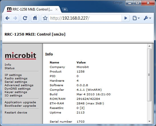
Application upgrade
The Software can be updated over the internet via the web interface when bugs are fixed and/or new functionality is implemented. You don’t have to be where the RRC-1258MkII is to do the updates.
First: Download the new firmware from www.remoterig.com and save the file on your computer. It has a name like RRC1258-CRC_v2.08_2010-03-04.bin
Start your web browser and connect to the RRC you want to update. Click on the link ‘Application upgrade’ to the left. Click on the ‘Browse’ button and select the file you downloaded a minute ago. When you have found it click on ‘Upgrade’. The new firmware is transferred to the RRC and is written into the flash memory of the RRC. The RRC will now restart, Note: Do not interrupt the upgrade process in any way.
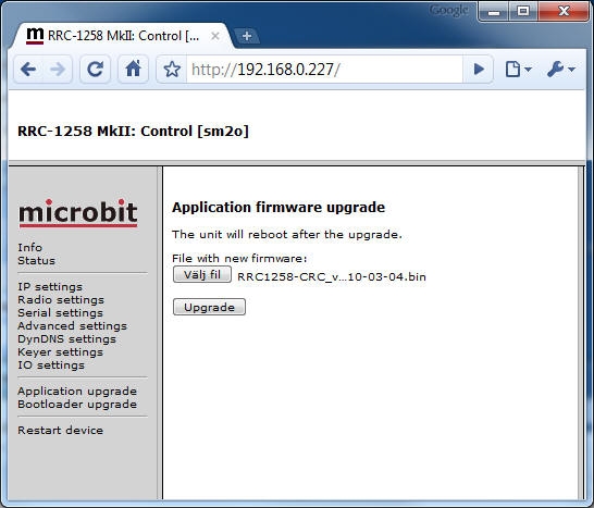
Wait a minute or two then connect to the RRC again and click on the “Info” link to the left and check that the Software version is updated. If it looks like it’s not updated empty the web browser cache, to prevent it from showing an old cached page. The update NEVER fails but the browser is a common problem.
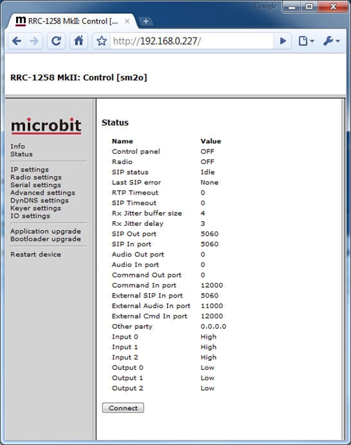
Status
On the status page you can check some parameters which can be useful when debugging etc. But the most important is that here is the “Connect” and “Disconnect” button used to connect or disconnect the Internet connection between the two units. When connecting you will see how the SIP-status is changed to “Connected/Transferring” if everything is OK. Here is also shown how your NAT-router has mapped the ports true the NAT-router.
Restart device
Can be used if you want to restart the unit without doing any changes (before apply changes).
Or just for ordinary reset.