Yeasu FT-100 can be used with Remoterig, but it’s a little bit more complicated as it’s not enough with putting straps in place, there need to be attached a few resistors and a optocoupler to the strapping socket. You also need to have the orginal separation cable witch are not available any more. You have to cut the cable in two pieces and crimp RJ12 modular connector to them.
The descriptions below shows the modifications needed for RRC:s of version V6 or earlier. If you have a RRC of V7 or later look here->
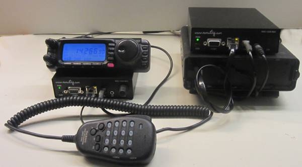
If you are willing to put the neccesary effort on the modifications the setup works great.
The software settings are the same as for FT-857.
Drawings for the cables (RRC <=V6 ) are available here ->
Drawings for strappings below.
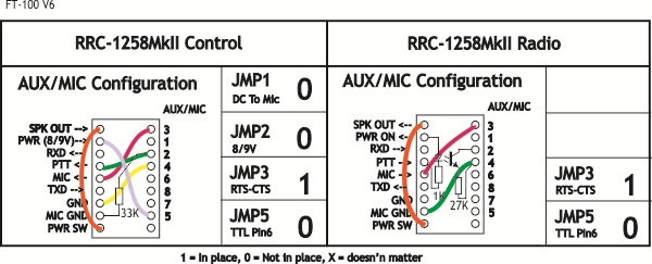
Above you can see how the straps and resitors should assembled. For the Radio-RRC i recommend to solder the components and straps in a 18 pin component socket, like the one on the picture below, so you do not need to solder direct to the socket on the PCB which then will be damaged.

Modifications of the Control-RRC circuit board
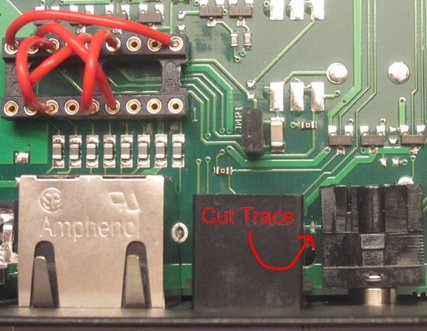
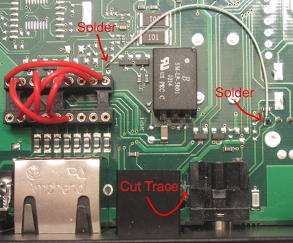
One trace on the pcb need to be cut to make it work. Locate the trace between the TTL connector and the Speaker connector ( see picture below). Use a sharp screew driver or the tip of a knife to carefully cut the trace. Do not pay any attention to the red straps on the picture below they are showing the FT-857 strapping.
Modifications of the Radio-RRC circuit board
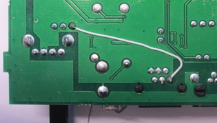
One 0 ohm resistor (jumper) must be removed and a wire must be solder between two pads. You need a fine solder iron and a short piece of insulated thin wire and maybe a little piece of tin. Don’t use any soldering braid or pumps they may damage the pcb.
– Remove the two 0 ohms “resistors” by heating the ends of the resistor, alternate from left to right end staying a few seconds at each end until the component come loose.

If you later want to reverse the modification, you can just solder a small copper wire between the pads instead of the 0R resistor.
– Solder the thin insulated wire between the solder pads as shown on the picture below. Do not pay any attention to the red straps on the picture below they are showing the FT-857 strapping.
If you later want to reverse the modification (the cut trace) it’s easiest to remove the PCB from the box and solder a wire between the two points showed in the picture below.