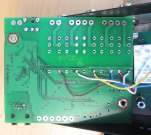
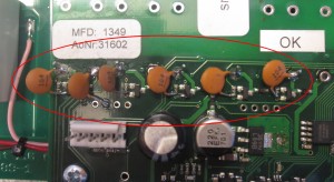
There are some inprovements that’s done to the the Antenna switch AS-1289 since the first was produced. This improvements are quite simple to do by yourself. 1. Reduce noise from the Control pcb heard in RX-mode. (Made in production from Rev 1.2) If you have a very low noise environment you may hear noise in your receiver which is picked up from the controlboard inside the Antenna switch. This noise can be reduced to 0 by grounding the control PCB. – Remove the two screws which holds the PCB in place and fold over the PCB so you can see the back of it. – Use a knife to scratch away the green soldermask around the two holes marked on the picture below so the bare copper will be visible (Be careful and only scratch near the holes) – When it’s done apply solder thin on the bare copper around the hole it so it looks like on the picture. – Then put the PCB back in place and tighten the screews quite hard to make good contact. The noise should not be noticeable any more. (click on the picture to get a high resolution version)  2. Prevent RF from randomly activate relays. (Made in production from Rev 1.3) In some situations RF can cause more than one relay to be activated. You can notice that from the front if more than one LED is lighting up when power is applied. This issue can be solved quite easily, by adding six 100nF ceramic capacitor on the control board like on the picture below. – Solder the capacitors between the solder point where the wire comes up from the relay board and the grounded side of the resistor. – The second capacitor (for 12V) from the left can be soldered to the hole as shown in the picture. (click on the picture to get a high resolution version)
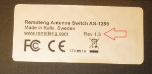
You can check which Revision you switch have on the bottom sticker. 
