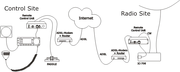
The idea of remote controlling IC-703/706 is simple. It’s just to extend the cord between the radio and the control panel using TCP/IP (Internet). When you press the Power button on the panel, the radio comes to life at the remote side and sound and panel info flows across the internet between the pair of RRC-1258MkII:s. The technical solution is the same as modern SIP-based IP telephones + a “little” extra. The look and feel of the panel is the same as if the panel was directly connected to the radio. There is no limitations, what is possible with the control panel locally connected to the radio is possible with the remote controlled radio.
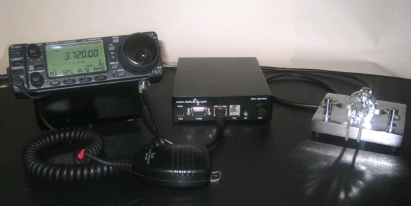
IC-706 Panel at Control site
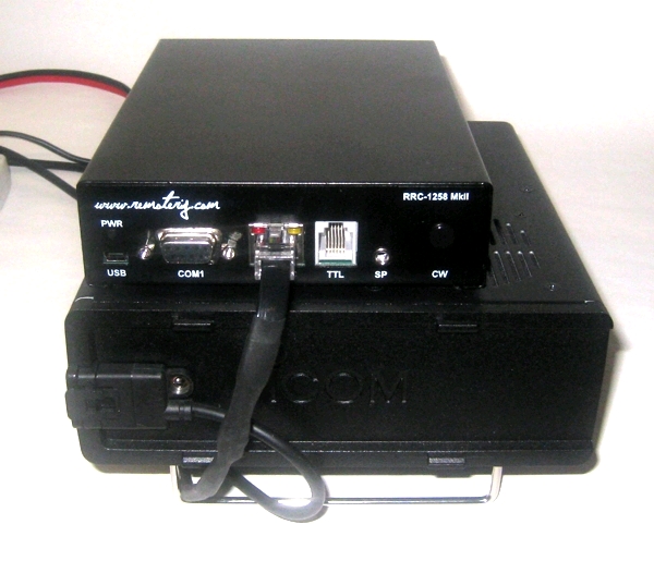
IC-706 radio unit with RRC-1258MkII
Preparation of IC-706 or IC-703 for remote control
(updated 09-11-29)
All necessary signals between the panel and the radio is connected thru the 8 wires in the cable OPC-581 from ICOM. We just need to cut it apart and connect a RRC-1258MkII in each end. The following signals is represented in the cable:
1. 8V power to control panel ( only when Radio is ON)
2. LRXD – serial data 19200 bps from panel to Radio
3. AF – Audio to speaker.
4. PWK – Power control. grounding it switch on the radio.
5. MICE – Mic ground
6. MIC- Mic Signal
7. GND
8. LTXD – serial data 19200 bps from radio to panel
Attention! the numbering above is for the RJ45 connector to RRC-1258 after converting the cable (Not the ICOM connector)
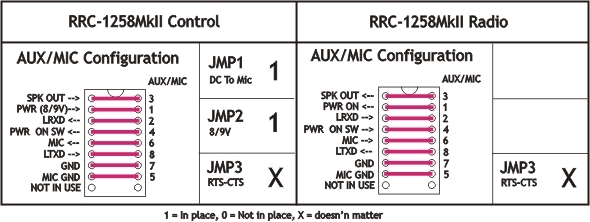
Before connecting the cables to radio and control panel you need to do some strapping inside the RRC:s. For instructions of how to open the RRC:s see “Open the box / straps” page. Down below is the strappings that need to be done described.
Cabling
The most complicated work before you can start the Remote control is to cut the cable (OPC-581or OPC-587) and join it together with the RJ-45 patch cable. The problem is that the ICOM cable is very soft and there is more sewing tread than copper wire. The copper wire is also varnished to make it even more difficult. But don’t be afraid it is possible.
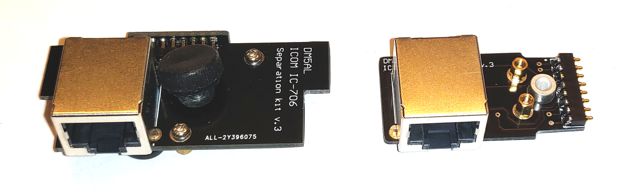
Note! today as the OPC cables are very difficult to find as they are no longer in production DM5AL has made an alternative solution which consist of two PCB:sMore info about how to use the DM5AL adapter with Remoterig is avaliable here =>
The easiest way is to cut a standard CAT-5 patch cable for computer networks and join them together with shrinking tubes. See detail information below.
Before you connect them to the RRC:s, please check the cables by connecting them together with the 2xRJ45 connector. If it works the, then the chance is good that it will work with the RRC:s also. Be aware of that the RRC:s is different, connect the cable to the corresponding RRC. Also pay attention to that a speaker or headset must be connected to the speaker jack on the IC-706 frontpanel otherwise the no audio will be sent from the microphone to the radio.
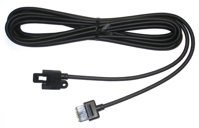
The cable between front and radio before it is cut apart. You have to buy this cable from your local ICOM-dealer (art no OPC-581 or OPC-587).
|
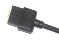
Connector at radio end.
|
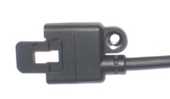
Connector at panel end.
|
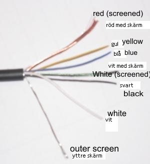 |
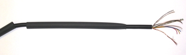
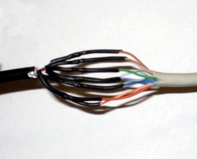
– Identify the end with the connector to the radio, se above. – Cut the cable apart, don’t make it longer then needed at radio end. The mic signal is sensitive of HF from antennas etc. as usually. – Take away about 40 mm of the outer covering. – Separate the shields from the inner wire, the red wire has a copper coloured shield and the white has a green shield. The shielded white wire is thinner than the white one without a shielding. That way you can identify them from each other. The outer shielding is not connected to the RRC. – Cut all wire to about 20 mm. Take way about 3 mm of the cover from each wire and tin-plate them. It’s not easy but it’s possible. – Also tin-plate the copper and green shielding |
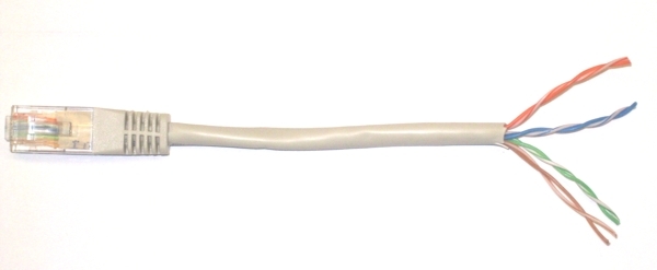
– Use the supplied CAT-5 cable cut of 10-15 cm from each connector and take away 40 mm of the outer cover.
– Separate the pairs.
– Take away 3 mm of the cover from each wire and tin-plate them.
– Identify the following colours:
1. Orange/White
2. Orange
3. Green/White
4. Blue5. Blue/White
6. Green
7. Brown/White
8. Brown
– First tread a 100 mm long 6,4 mm shrinking tube on the separation cable.
– Then tread a 80 mm long 6,4 mm shrinking tube on the separation cable.
– Solder them together, follow the drawing drawing.
– Tread the shrinking tubes over the soldered joints and shrink them with hot air.
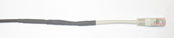
– Tread the 6.4 mm shrinking tube over the joint and shrink it with hot air.
– Tread the second shrinking tube over the first and shrink them with hot air
– The first cable is now finished, Do the same with the other part. The one with the connector to the panel.
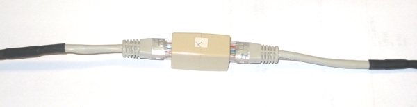
When you have finished both cables , connect them together with the supplied RJ45 extender.
– Check the cable with an ohm-meter. You should have connection from pin 1 at radio end to pin 1 at radio end etc. Also check for short circuits between the pins.
– Connect the cable between panel and radio and check the functionality. Don’t forget the microphone. ( this should be done without involving the RRC.s at this moment.
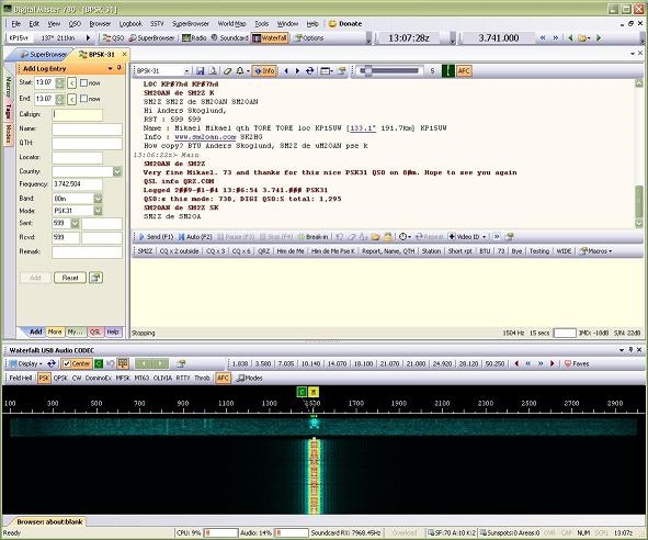
Using digital modes with remote controlled IC-706
My personal interest for digital modes is limited to PSK31 in NAC-28 contests. Anders SM2Z begin_of_the_skype_highlighting end_of_the_skype_highlighting who have made thousands of QSO: using digital modes before are now using a remote control IC-706. He has worked lot of QSO:s using different modes with the remote IC-706 and it seems to work as good as with a local radio. Since digital modes is not suffering from delays it’s more depending on audio quality. We recommend using at least Quality=2 when working digital.
The setup is very easy, you only need a CAT-5 patch cable with RJ45 connector, connected between the SignaLink and the IC-706 Control panel. The jumpers inside the SignaLink must be set as shown in the drawings below. Be aware that the Mic gain and Volume controls have influence over the audio signals. The Speech compressor should be switched of. We have used Digital Master 780 and HamRadioDeLuxe installed under Windows XP.
If you don’t use IC-706 you can of course connect direct to the RRC-1258MkII
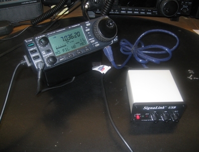
The setup. here with SignaLink USB connected to the control panel with a CAT-5 patch cable.
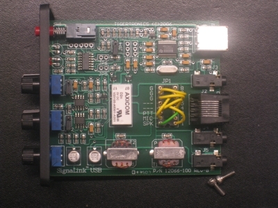
The jumpers inside the SignaLink
RJ-45 Mic Connector (use SLUSBRJ4, SL1+RJ45, SL1-RJ45 or SLCABRJ4)

How to set the jumpers (from Tigertronics website).