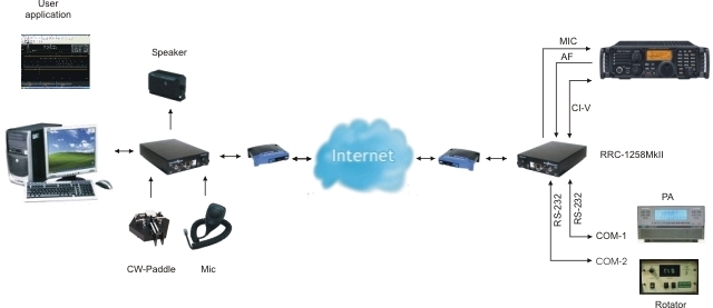
RRC-1258MkII also supports the CI-V protocol used by almost every ICOM radio. Then you have to use a PC-software ex. HamRadioDeLuxe or a similar rig control software at the control site. All audio and data communication goes true the RRC:s so you don’t have to worry about the audio quality. No more problems with soundcards and Skype etc. And most important, you don’t need a PC at the remote site.
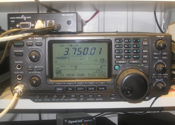
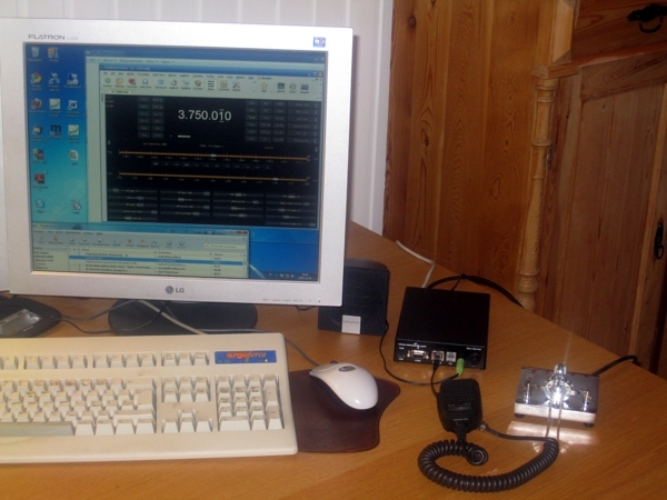
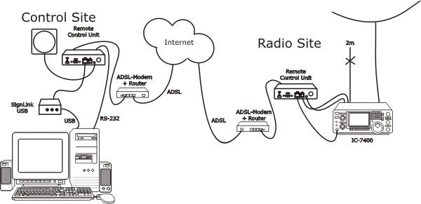
RRC-1258MkII connected to my IC-7400
When you want to control ICOM radios with the RRC-1258MkII via the CI-V protocol, you connect a standard RS-232 cable between the PC and the COM 2 connector on the back of the Control-RRC. From the Radio-RRC:s TTL jack to the radios CI-V jack you need to make a simple cable. The cable should have a 4/6 modular connector in one end and a 3.5 mm stereo plug in the other end. The 3.5 mm plug is connected to the radio CI-V jack.
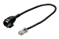
The microphone can be connected direct to the Control-RRC AUX/MIC jack, if you have a mic with RJ-45 connector like the HM-103. If you have a microphone with a circular connector like HM-36 you can buy a adapter cable OPC-589 from ICOM or make one by your self.
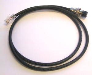
Between the Radio-RRC AUX/MIC jack and the radios microphone jack you can connect a standard patch cable if the radio have a RJ-45 jack. If the radio have a circular microphone jack you need to make a adapter cable by your self or buy one from our webshop. I make it by your self make the cable as short as possible to prevent it from picking up HF.
The speaker is connected direct to the SP-jack on the front of the Control-RRC with a 3.5 mm stereo plugg. The speaker signal from the radio to the
The speaker signal from the Radios ext. speaker jack to the Radio-RRC SP jack is connected via a standard “off the shelf cable” with 3.5 mm stereo plugs in both ends.
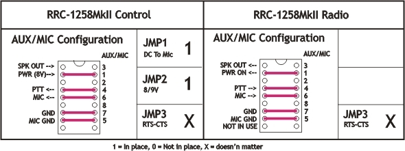
Strapping
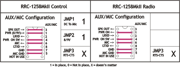
Before connecting the cables to radio and control panel you need to do some strappings inside the RRC:s. For instructions of how to open the RRC:s see “Open the box / straps” page. Down below is the strappings that need to be done described.
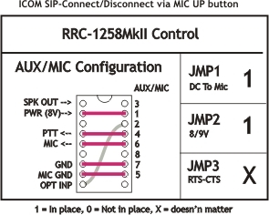
If you want to be able to Connect resp. Disconnect the SIP-connection via the Microphone UP button you can add the grey strap in the control RRC. But don’t press the button when you are in QSO.
f you make the Mic cables by your self you can test them with them with the 2xRJ-45 extender before connecting them to the RRC:s.
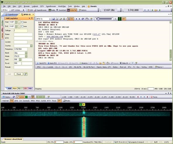
Using digital modes with a remote controlled ICOM ( generic ICOM mode=1)
(updated 100102)
It’s quite simple to use the Remoterig boxes for digital modes. You connect a patch cable of CAT-5 type between the Signal link and the RRC. And a RS-232 cable for Control of the radio and USB alt audio cables between the PC and the SiglaLink depending on which type is used. The cable between the Radio-RRC and the radio should include the 8V signal then the Control RRC will let out 8V to the SignaLink. The jumpers inside the SignaLink must be set as shown in the drawings below. Use minium audio quality 2 (8 kHz 16 bit). Be aware that the Mic gain and Volume controls have influence over the audio signals. The Speech compressor should be switched of. We have used Digital Master 780 and HamRadioDeLuxe installed under Windows XP.
Cabling SignaLink -> RRC-1258MkII and RRC-1258MkII -> Radio
The RRC must be strapped also
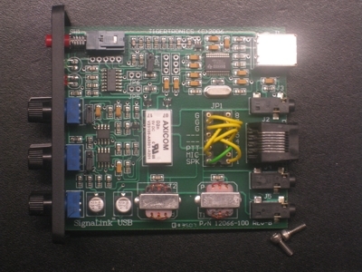
SignaLink – RRC-1258 RJ-45 AUX Connector


How to set the jumpers (from Tigertronics website). Same as for IC-706)