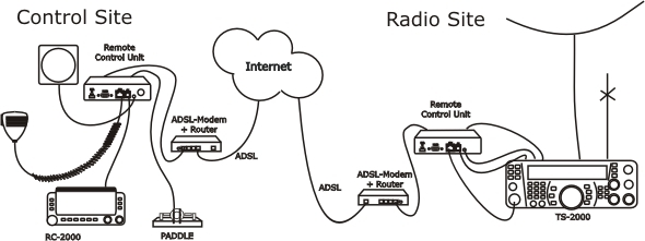
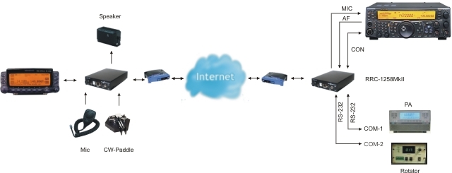
The technical solution for TS-2000 is the same as for TS-480 and IC-706 but TS-2000 has a special control panel witch works in parallel with the front panel controls on the Radio. This means that if you have the TS-2000 at your summer QTH you do not need to take the control panel with you when you want to use the TS-2000 locally. We replace the cable between panel and radio with to RRC-1258, one connected to the control panel and one connected to the radio. No PC is needed at all. When you press the Power button on the panel, the radio comes to life at the remote side and sound and panel info flows across the internet between the pair of RRC-1258:s. The technique is the same as modern SIP-based IP telephones + a little extra. The look and feel of the panel is the same as if the panel was directly connected to the radio. The TS-2000 is quite simple to setup because you do not need any special cable. You can make the cables by your self using simple and cheap RJ-45 and RJ-12 connectors.
 |
 |
||
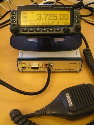
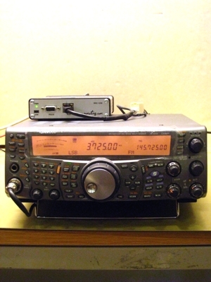
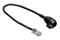
| TS-2000 control panel and RRC-1258 |
|
Preparations of TS-2000 for remote control (mode=8)
(updated 10-01-17)
All necessary signals between the panel and the radio is connected thru the 4 wire cable between the control panel and the radio. We just need to cut it apart and connect a RRC-1258MkII in each end. The following signals is represented in the cable.
| RJ12 Radio |
Modular 4/4 Control Panel |
Description |
| 1 | ||
| 2 | 1 | 8V power to control panel ( always present) |
| 3 | 2 | GND |
| 4 | 3 | RDO – serial data 57600 bps from radio to panel |
| 5 | 4 | TDO – serial data 57600 bps from panel to radio |
| 6 |
The easiest way to make these two cables from Control panel to Control RRC TTL-jack and from Radio-RRC TTL-jack to radio is to cut the cable supplied by Kenwood into two pieces. You only have to crimp two new 6/6 modular connectors on the cables. Don’t make the one between Radio-RRC and radio to long.
The long Microphone extension cable supplied by Kenwood can also be used between Radio-RRC AUX/MIC jack to the radio Mic jack. Probably you need to cut in later to prevent it from picking up HF from your antennas.
The microphone can be connected to the Control-RRC AUX/MIC jack using the the adapter cable MJ-88 supplied by Kenwood with your RC-2000.
The speaker supplied with the RC-2000 is connected to the 3.5 mm SP-jack on the front of the Control-RRC.
The speaker signal from the TS-2000 ext. speaker jack to the Radio-RRC SP jack is connected via a standard “off the shelf cable” with 3.5 mm stereo plugs in both ends.
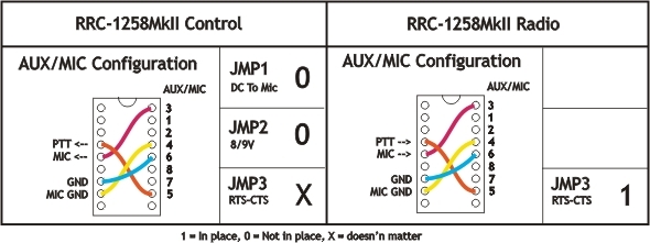
Before connecting the cables to radio and control panel you need to do some strappings inside the RRC:s. For instructions of how to open the RRC:s see “Open the box / straps” page. Down below is the strappings that need to be done described.
Eg. you should not need to produce any cables but if you want, check the drawings below
Attention! Always check the users manual for updated drawings before starting to make cables