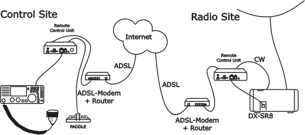

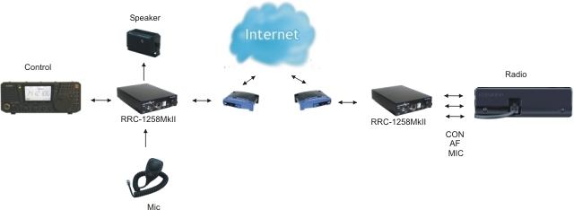
The technical solution for Alinco DX-SR8 is the same as for IC-703/706, TS480 and TS-2000. All those transceivers are built in the way that the control panel is working separated from the radio unit itself. We replace the cable between panel and radio with two RRC-1258MkII, one connected to the control panel and one connected to the radio. No PC is needed at all. When you press the Power button on the panel, the radio comes to life at the remote side and sound and panel info flow across the internet between the pair of RRC-1258MkII:s. The technical solution is the same as modern SIP-based IP telephones + a little extra. The look and feel of the panel is the same as if the panel was directly connected to the radio. The DX-SR8 is the easiest of all to adapt because you only need two standard patch cables with RJ-45 connectors, nothing else.
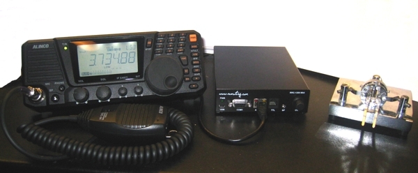
Alinco DX-SR8 control panel and RRC-1258MkII
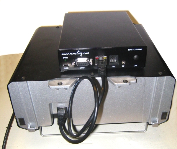
Alinco DX-SR8 Radio unit and RRC-1258MkII
Preparations of DX-SR8 for remote control (mode=12)
(updated 10-05-17)
All necessary signals between the panel and the radio is connected thru the 8 wire standard patch cable between the control panel and the radio. We just need to use two standard patch cables , one between the Control panel and the Control-RRC and the other one between the Radio-RRC and the radio. The following signals is represented in the cable. Convenient for travelling is that the speaker is already present on the back of the control panel so there is no need for a extra speaker even if a bigger separate speaker gives better audio.
8-pol Modular RJ45
1. TXD data from radio to control panel
2. RXD data from Control panel to radio
3. 8V power to control panel (when radio is switched on)
4. Not in use
5. Mic signal / PWR On/off button
6. GND
7. AF – Audio to speaker.
8. SPK GND- Speaker ground
Before connecting the cables to radio and control panel you need to do some strappings inside the RRC:s. For instructions of how to open the RRC:s see “Open the box / straps” page. Down below is the strappings that need to be done described.
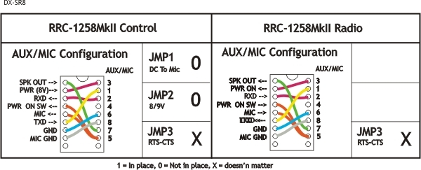
Attention! Always check for updated drawings before starting to make cables
Cables control panel to RRC-1258MkII
No drawings needed only standard patch cables are used
Cables RRC-1258MkII to Radio
No drawings needed only standard patch cables are used
The Control-RRC are powered with a simple 13.8V (10-18V) power supply. The display (backlighter) and speaker amplifier needs lot power so use min 1A.
A switched 13,8V/1.5A FRIWO Power supply can be bought together with the RRC:s to a reasonable price.